APPENDIX A
SHIPBOARD COMMUNICATIONS EQUIPMENT
A.1 SHIPBOARD COMMUNICATIONS EQUIPMENT
Submarine shipboard communications systems consist of RF antennas and radio room
equipment, both RF transmitters/receivers and baseband suites. The following sections describe
the current baseline submarine communications capabilities and list the current (POM 96)
programs. This appendix is organized into five major sub-sections. Sub-section A.2 lists the
current communications circuit capabilities of the submarine ECS and describes the rack
arrangements for each submarine class. Sub-section A.3 describes the current submarine
antenna program. A.4 provides an overview of the current Advanced Technology
Demonstration (ATD) in the area of submarine antennas. In sub-section A.5, shipboard
equipment procured for submarines by SPAWAR PMW 173 is listed. Lastly, sub-section A.6
describes shipboard equipment procured for submarines by other SPAWAR program offices and
DOD organizations.
A.2 CURRENT SUBMARINE COMMUNICATIONS CAPABILITIES
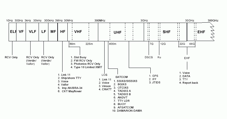
Submarines communicate via multiple, complementary RF systems, covering nearly all the
military communications frequencies. Figure A-1 lists the current submarine communications
systems and their associated RF frequency band. Because of these limitations, no one
communications system or frequency band can support all submarine communications
requirements. For example, UHF SATCOM provides a relatively high data rate but requires the
submarine to expose a detectable mast-mounted antenna, degrading its primary attribute �
stealth. Conversely, extremely low frequency (ELF) and VLF broadcast communications
provide submarines a high degree of stealth and flexibility in speed and depth, but are low data
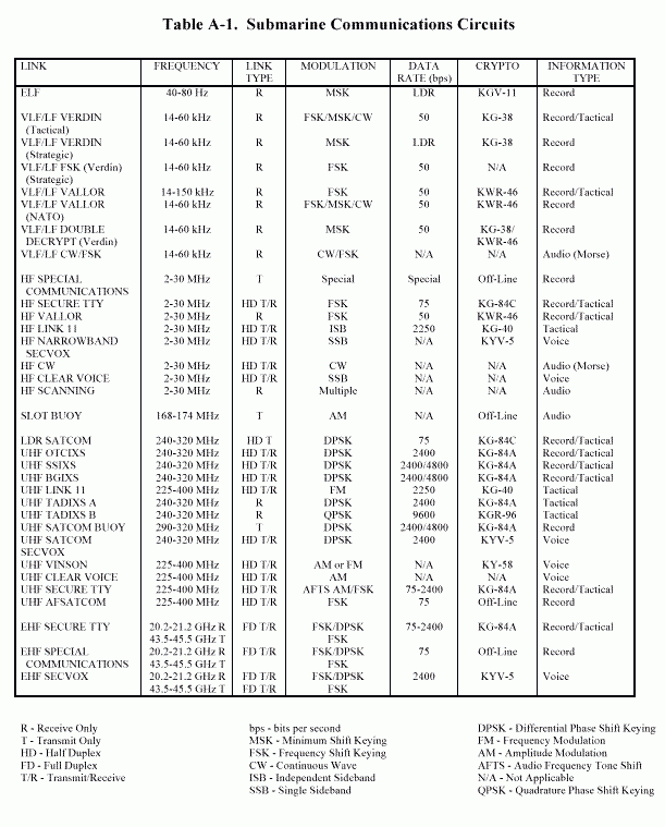
rate, submarine-unique and shore-to-submarine only. Table A-1 lists the unclassified
characteristics of the communications circuits used by TRIDENT and LOS ANGELES class
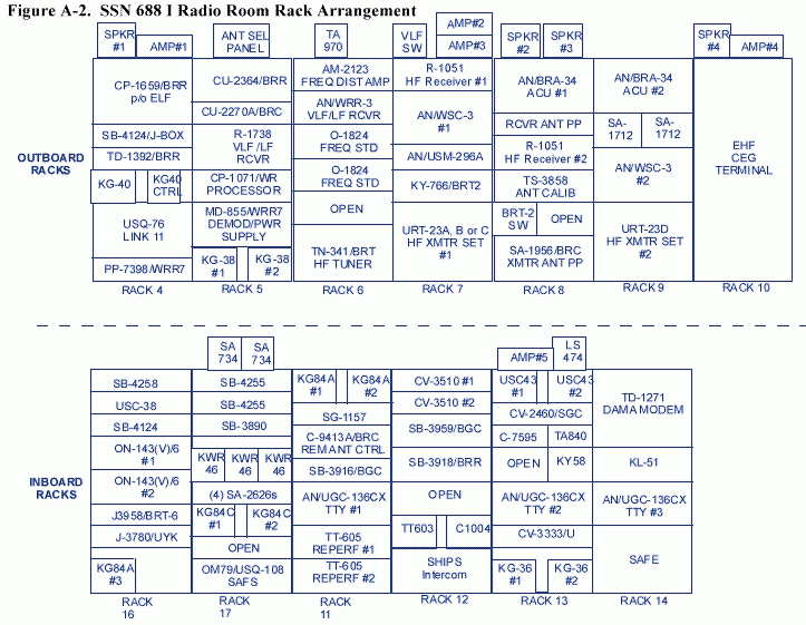
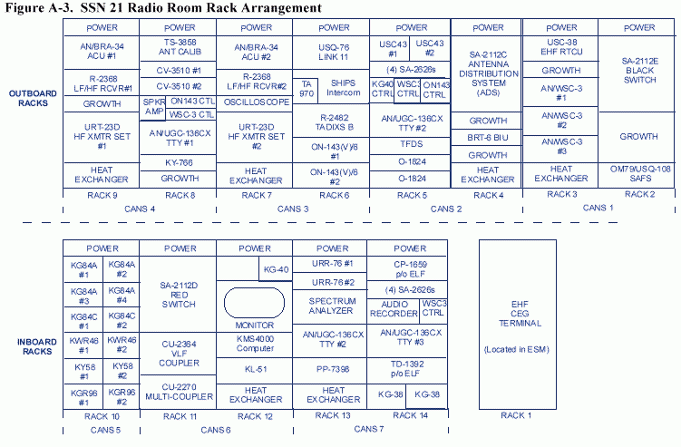
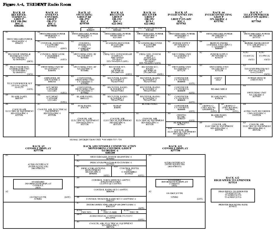
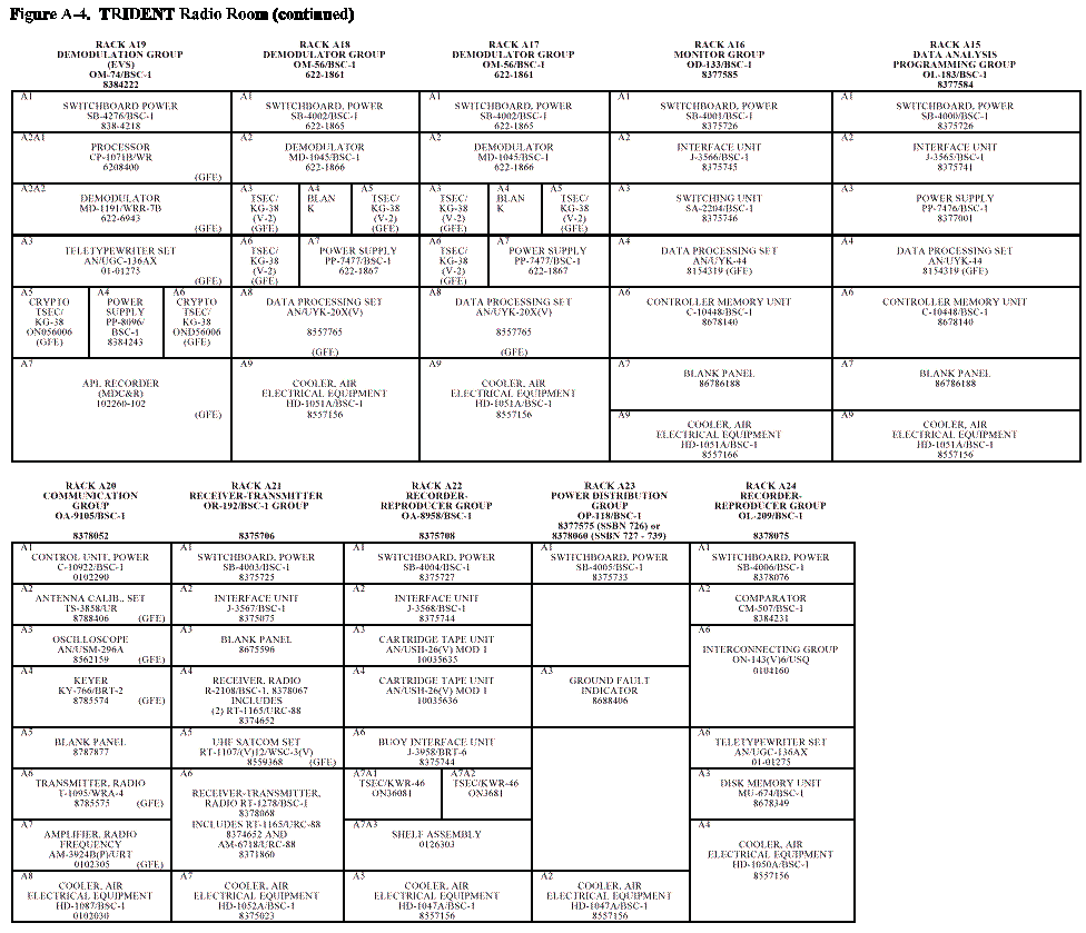
submarines. Figures A-2 through A-4 describe the SSN 688I, SSN 21, and TRIDENT SSBN
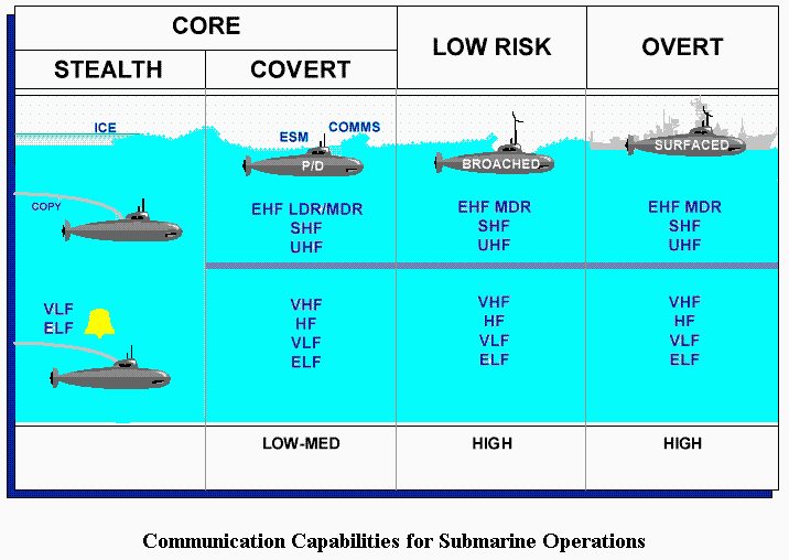
radio room equipment rack layouts. Figure A-5 depicts the notional speed and depth limitations
placed on the submarine by various communications circuits.
A.3 SHIPBOARD ANTENNAS
The SIAS Program provides SSN and SSBN submarines with new and improved antenna
systems to support multifunction information exchange (including communications, navigation,
and identification) capabilities with aircraft, ships, other submarines, and shore stations in
support of submarine warfare operational doctrines. The SIAS Program also supports
development of antenna distribution systems to permit optimum signal distribution. The NUWC
Division Newport is the Technical Development Agent (TDA) for submarine antennas and acts
as the Navy�s point of contact for submarine antenna programs. The following subsections
provide detailed information on existing submarine antennas, the antenna suites of each
submarine platform, and the antenna ATD program. Current antenna development programs are
described in Section 4, these include the Submarine HDR SATCOM antenna, the Improved
AN/BRA-34 antenna, the ADS, the upgrade to the AN/BST-1 SSBN emergency buoy, and the
antenna systems engineering efforts.
A.3.1 Existing Submarine Communication Antenna Systems
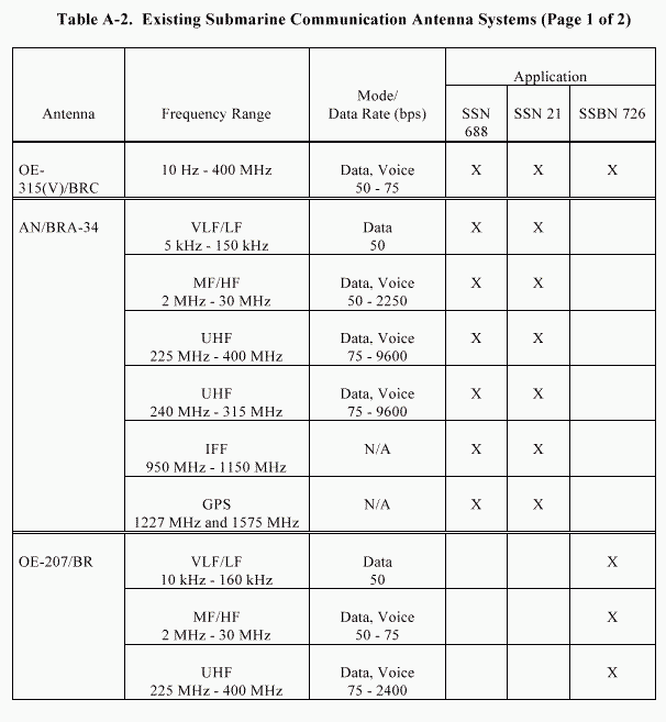
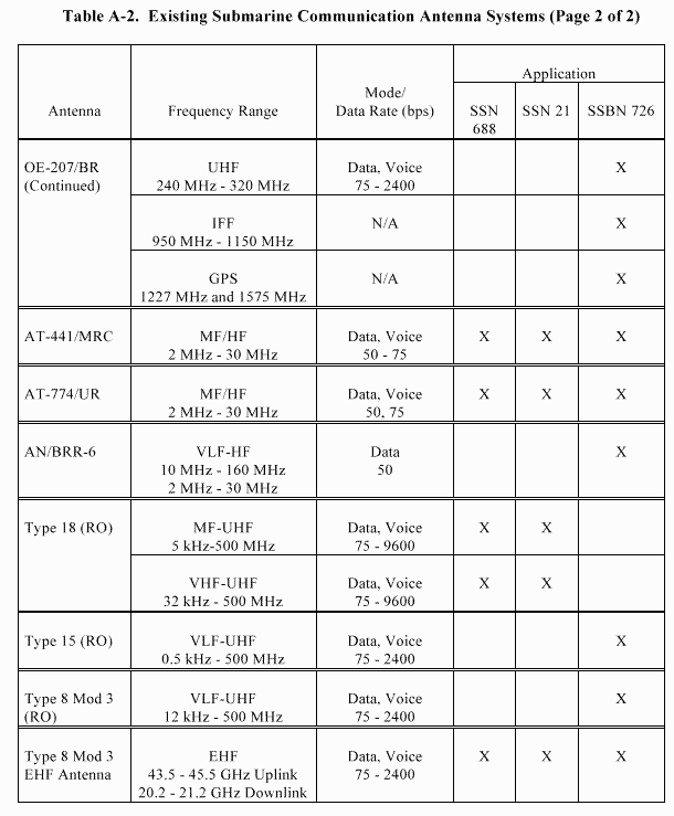
Table A-2 provides a summary of the current and near-term submarine communication antennas.
A.3.1.1 SSN 688-Class Capabilities
SSN 688-Class submarines are currently equipped with two multifunction masts (AN/BRA-34)
which provide a capability to communicate on two-way HF and UHF nets and a receive-only
VLF/LF and Global Positioning System (GPS) capability. AN/BRA-34 DAMA modification
kits are being installed to provide DAMA compatibility. This antenna also provides an IFF
capability. The Type 18 periscope provides a limited VLF/LF/VHF/ UHF receive capability and
a marginal transmit capability at VHF. In FY93, installations of AN/USC-38(V)1 EHF terminals
began on this class of submarine. The first EHF terminals use an EHF antenna mounted on the
top of the Type 8 Mod 3 periscope and are capable of operating with FLTSATCOM EHF
Package (FEP) and Milstar I LDR satellites. The SHF/EHF HDR multiband antenna, when
developed, will replace one AN/BRA-34. The SSN�688 has an OE-315(V)/BRR high speed
buoyant cable antenna (HSBCA) system and carries AN/BRT-6 expendable UHF SATCOM
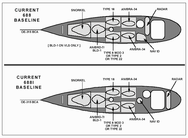
buoys. Figure A-6 shows the layout of the current baseline SSN 688 and SSN 688I sail
configurations.
A.3.1.2 SSN 21-Class Capabilities
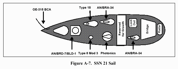
The baseline SSN 21 communications antenna suite is the same as for the SSN 688-Class
submarine; Figure A-7 shows the baseline sail configuration.
A.3.1.3 SSBN 726-Class Capabilities
The current SSBN 726-Class antenna suite has two multifunction masts (OE-207/BR) for
communications at periscope depth. The OE-207/BR multifunction mast provides the same
communications capability as the AN/BRA-34. The difference in the two masts is the length of
the OE-207/BR for integration into the TRIDENT sail. TRIDENT submarines are scheduled to
receive the AN/USC-38(V)1 EHF terminal with the Type 8 Mod 3 periscope
EHF antenna. The SHF/EHF HDR multiband antenna, when developed, will be added as a new
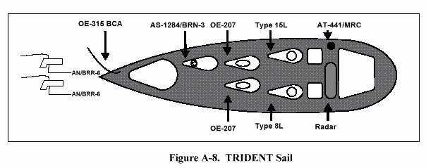
mast. This class of submarines also has the OE-315 HSBCA. The SSBN has two AN/BRR-6
towed communications buoys. Figure A-8 shows the layout of the current baseline SSBN 726
sail.
A.3.1.4 NSSN Capabilities
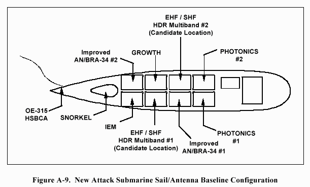
Figure A-9 shows the current baseline sail configuration for the new SSN. The SHF/EHF HDR
multiband antenna will be added and located in a modular antenna bay; the exact location has
not been established.
A.3.1.5 Antenna Inboard Switching And Distribution
Switching and antenna distribution is accomplished in the SSN 688 radio room by manual
switches. The SSBN 726 IRR has a limited capability for remote switching and tuning. The
SA-2112 Switching System has been developed and will be used in the SSN 21 radio room.
This unit has limited remote switching capability, limited flexibility, and is not compatible with
future open architecture design concepts. The ADS program, described in Section 4, will
provide automated switching and antenna tuning for all submarine platforms as an element of the
SCSS ECS.
A.4 Advanced Antenna Development
A.4.1 Submarine Super High Frequency Phased Array Antenna Advanced Technology
Demonstration
A.4.1.1 Overall Advanced Technology Demonstration Objectives
The objective of this ATD is to design, build, and demonstrate a submarine phased array
antenna. This antenna would allow two-way communications at SHF via satellite at higher data
rates than currently available to the submarine. In addition, Low Temperature Co-fired
Ceramics (LTCC) will be demonstrated as a low cost, thin, lightweight solution to submarine
phased array antenna design.
A.4.1.2 Advanced Technology Demonstration Technical Objectives
Submarine satellite communication data rates are limited by the lack of a large aperture antenna.
Current satellite resources, whether military or commercial, are limited in the amount of effective
isotropic radiated power (EIRP) provided in the space-to-earth segment. Large antenna gains are
therefore required at the submarine, which in turn requires large aperture antennas. To be
interoperable, submarines require antennas with performance comparable to the least-capable
TOMAHAWK-equipped surface ship. As a reference point, the least capable TOMAHAWK-equipped
surface ship uses a four-foot reflector antenna for operation over the DSCS.
The two primary antenna designs which provide high gain and directivity are phased arrays and
reflectors. Reflector antennas are commonly used on surface ship platforms, but they are
typically bulky, difficult to store in a small volume, and require mechanical steering. Phased
arrays are versatile, allowing electronic beam scanning, conformal design flexibility, and
modular construction to improve stowability. Although phased arrays have been expensive in
the past, recent technological breakthroughs have the potential to significantly reduce the design
and manufacturing costs of phased arrays and their components.
This ATD is also pursuing the development of a dual band phased array module which would
operate over DSCS and Commercial Ku bands. The ATD will develop a LTCC multilayer
circuit substrate that will support multiple antenna elements and two or more communications
bands. The LTCC circuit is very compact and will be packaged for the submarine environment.
This technology would enable communications over two separate satellite systems
simultaneously.
A.4.1.3 Schedule/Demonstrations
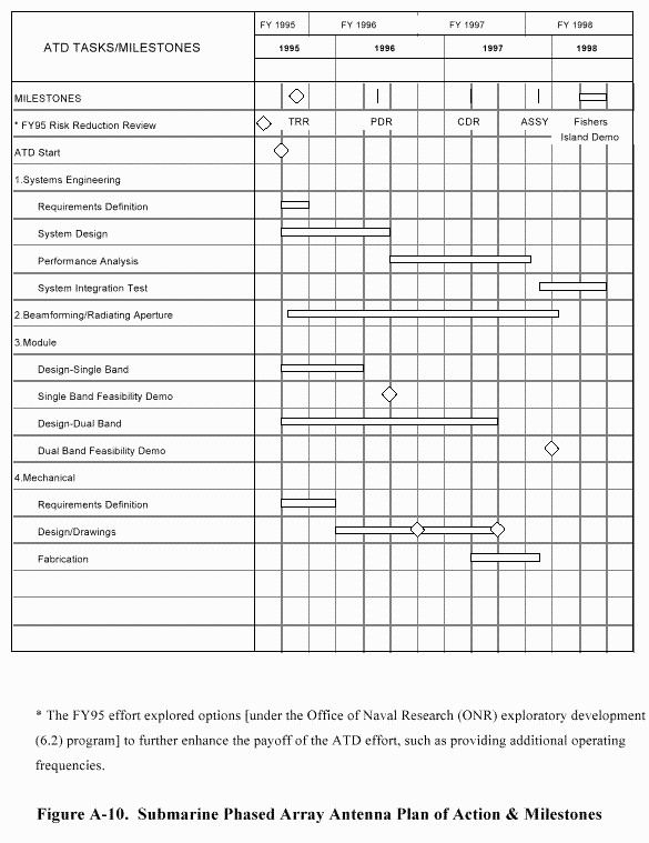
A high level schedule and milestone chart is shown in Figure A-10. Preliminary reviews will be
held prior to the start of the ATD to address requirements definition and high-risk areas. Major reviews will be held during the ATD at the end of FY96 (Preliminary Design Review (PDR) and
at the end of 3rd Qtr FY97 (Critical Design Review (CDR). These reviews will cover the entire
scope of the ATD and will serve as the decision points for the final requirements definition and
risk mitigation.
A.5 PMW 173 RADIO ROOM EQUIPMENT PROGRAMS
A.5.1 Submarine LF/VLF VMEbus Receiver
The SLVR is intended to provide the next generation VLF/LF receiver that will be used in 688
and SEAWOLF class SSNs and TRIDENT SSBNs. The SLVR will meet environmental, noise,
EMI/EMC, TEMPEST and other requirements of targeted platforms. BIT, BITE, Mean
Corrective Maintenance Time for Operational Mission Failures (MCMTOMF), MTBOMF,
operational availability, and other system requirements will also be addressed during SLVR
development. The SLVR will be capable of receiving and processing all Navy, special, and
NATO modes presently required, and will be easily adaptable and expandable to future
requirements through the use of COTS hardware and GOTS software. SLVR is based on two
commercial, open systems architectures: VMEbus and VXI. VXI is used for the RF portion of
the receiver, with VMEbus used for the message processing, cryptographic and user interfaces.
The all-COTS demodulator and processor hardware can be programmed, at a later date, for use
in a multi-band receiving system. Anticipated SLVR P 3 Is are the inclusion of a COTS VXI-based
MF/HF receiver and addition of an ELF capability to allow removal of the OR-279.
Developmental Testing (DT) of SLVR is scheduled for early FY97 and a production version of
the DT model receiver will form the basis for an VLF/LF IOC in FY99.
A.5.1.1 ELF Receiver (OR-279/BRR)
The ELF receiver group is currently installed on all TRIDENT SSBNs and is being installed,
under SHIPALT A3125, on all 688-class SSNs. The OR-279/BRR is used with either the
OE-315 floating wire antenna or the HSBCA. The ELF SHIPALT will be complete by FY95.
The ELF band provides a one-way, low speed communications capability to submarines at speed
and depth.
A.5.1.2 Minimum Essential Emergency Communications Network
This program identifies and develops improvements to Minimum Essential Emergency
Communications Network (MEECN) for transmission of EAMs via tri-service VLF/LF
transmission systems. The purpose of these improvements is to increase EAM delivery
reliability and reduce delivery time while retaining interoperability between the various
equipment of the services. Program efforts include developing new MEECN communications
modes and improved signal processing techniques in response to evolving threats and technical
advancements. The HIDAR will be operationally fielded in FY96.
A.5.1.3 VERDIN/Enhanced VERDIN System Receiver
VLF Digital Information Network (VERDIN) is a VLF/LF communications system that provides
secure command and control communications to the strategic and tactical submarine forces and
the airborne VLF relay aircraft (TACAMO). VERDIN is being upgraded in accordance with
STANAG 5030 to provide U.S./NATO interoperability for SSNs. The Enhanced VERDIN
System (EVS) is a VERDIN product improvement developed to provide increased performance,
reliability, and maintainability; a capability to process JCS directed 1600 baud mode MEECN
interoperability; automatic mode recognition; message compression; automatic recovery/restart
capabilities, giant step, high speed run up; and improved operator features for performance
monitoring and fault location. The program replaced existing VERDIN processors, and
modified the VERDIN equipment with a field change to permit 1600 baud MEECN
interoperability on strategic submarines and TACAMO aircraft. The VERDIN/EVS receiver
(R-1738) noise reduction circuit (NRC) field change has been incorporated into the EVS. This
mod improves receiver performance in atmospheric noise. The non-linear adaptive processor
(NONAP) has been provided to increase operational flexibility for submarines by pre-detecting
differences between the desired VLF signal and noise interference; thereby enabling reception of
messages during severe interference.
A.5.1.4 Submarine Message Buffer
The SMB will provide a means of non-volatile message storage and message generation and
processing in LOS ANGELES and SEAWOLF class submarine radio rooms. The SMB will
replace obsolete and unsupported paper tape data storage, the AN/UGC-136CX SKP and
generally improve radio room operability. The SMB utilizes COTS and GOTS hardware and
software products providing an easy migration path to current state-of-the-art systems. The
system will be capable of performing all message handling functions which include: (1) receive
and transmit on four asynchronous channels simultaneously; (2) file manipulation capabilities
via a COTS relational database which will provide powerful relational query capabilities,
multiple levels of ordering of query results, and fast data retrieval in response to complex
queries; (3) word processing functions such as composing, editing and validating preformatted
messages via commercial and military editors; (4) mass storage; and (5) secure message
distribution via a shipboard LAN which will be DMS compliant using X.400/X.500 protocol.
Additionally, SMB will provide a JMCIS compliant graphical user interface (GUI), an interface
to the BBS INM, ZBO management, guard list management, message file splitting, message
redundancy analysis, database purge, and RAM purge for security. SMB will also provide a
subscriber to the Navy EHF Communications Controller (NECC) to access EHF and UHF packet
switched information as part of the overall integration effort with the SCSS. SHIPALT 3748 is
installing the SMB and is expected to be completed by FY97.
Future improvements to the SMB include: (1) porting of the SMB to a VME environment,
(2) improved security features via compartmented mode workstations and a distributed MLS
database, and (3) evolution to a mission critical system.
A.5.1.5 Time and Frequency Distribution System
The Time and Frequency Distribution System (TFDS) will provide precision time and frequency
input required by equipment in communications, electronic warfare, periscope, navigation,
combat, and ship control systems aboard attack and TRIDENT class submarines. The TFDS
hardware will be an NDI. The TFDS will be capable of automatic or manual selection of inputs
from cesium beam standards (O-1824/U or O-1695/U) or GPS. Using inputs from the selected
external standard, TFDS will be capable of distributing up to 20 5-MHz square wave (SW), 5 1-
MHz SW, 5 100-kHz SW, 5 1-ppm, 10 1-pps, 16 Binary-Coded Decimal (BCD) time code (TC),
and 5 TF signals. The TFDS will be a modular system with no single point failure, and which
can be expanded by adding additional modules.
A.5.1.6 SA 2626/BR Red/Black Isolation Switch
The SA-2626, being installed under SHIPALT SSN 3837, provides the capability to manually
switch red and black baseband data to the Submarine Keyboard Printer (SKP), while ensuring
the printer memory is cleared before shifting between red (un-encrypted) and black (encrypted)
modes. The SA-2626 SHIPALT is applicable to all 688-class SSNs and required prior to several
other SHIPALTs (SMB, SSN Air Force SATCOM System [SAFS], KY-766). It is scheduled to
complete by FY97.
A.5.1.7 Baseband System
The BBS program will procure three sub-systems: (1) Packet switches; (2) Circuit switches; and
(3) an INM providing automated technical control of both switch types and selected legacy
equipment. There will be a NDI and COTS-based procurement which will automate submarine
radio room assets, provide remote control switching operation, allow preset configurations for
quick reaction times, and reduce needed rack space. The program will replace 11 different
switches presently installed in the SSN 688 radio room with one black switching matrix and one
red switching matrix. The present switching systems have insufficient throughput, capacity,
flexibility, and operability to handle future radio room switching requirements.
During FY94 and FY95, PMW 173 investigated possible BBS architectures and technologies
prior to a MS-III decision and contract award in FY96. The BBS program will investigate OSA,
NDI switching systems and will evaluate potential switching technologies through a prototype
on-board a SSN 688I class submarine. This prototype will evaluate: (1) the NECC, a
Transmission Control/Internet Protocol (TCP/IP) packet switch; (2) a prototype circuit switch,
based on a hybrid of a VMEbus circuit switch and a COTS matrix switch; and (3) a COTS-based,
JMCIS compliant INM, executing technical control of the radio room via SNMP over an
Ethernet (IEEE 802.3) LAN. Additional equipment being fielded includes the GFCP, R-2368
MF/HF receiver, and the SMB. This BBS prototype is being used to refine submarine BBS
requirements, prior to the BBS Request for Proposal (RFP) and contract award, anticipated in
FY96. The BBS prototype will also be used by Commander, Operational Test and Evaluation
Force (COMOPTEVFOR) to conduct an Operational Assessment of the BBS system. The
prototype systems and lessons learned will be made available as GFI during the BBS
procurement.
A.5.1.8 Submarine LF/VLF Signal Recorder
An LF/VLF Wideband Signal Recorder is used by the Fleet Ballistic Missile (FBM)
Communications Continuing Evaluation Program (FBM COMM CEP) to conduct special tests
and to assist in failure analysis. The Test Director for this program is COMSUBLANT (N9) and
Johns Hopkins University Applied Physics Laboratory (JHU/APL) is the evaluating agent. The
FBM COMM CEP is used as an integral part of Navy�s strategic communications monitoring,
assessment, and reliability performance evaluation for the TRIDENT IRR. Therefore, the
replacement TRIDENT IRR SCSS must contain an LF/VLF Wideband signal recorder.
An improved Submarine LF/VLF Signal Recorder is under consideration for both SSBNs and
SSNs which will provide recorder and analyzer functionality. This improved Submarine
LF/VLF Signal Recorder design will be based on a VMEbus hardware design and will be
compatible with the SCSS radio room architecture design. An initial implementation alternative
for this signal recorder will make it part of the SLVR program as a P 3 I initiative.
Capabilities this improved system could provide submarine operators include: recovery of
EAMs lost through operator errors or temporary equipment outages; display of signals of interest
and sources of interference, including EMI, for radio room operators with cues to permit
optimization of receiving equipment; providing a mechanism for special test data collection;
crew training using realistic recorded scenarios; and the ability to generate test signals for
troubleshooting and maintenance of radio room RF equipment. This advanced recorder/analyzer
system is undergoing prototype development testing at JHU/APL and is not yet funded or
approved for fleet introduction.
A.5.1.9 TRIDENT Integrated Radio Room
The TRIDENT IRR, frozen in FY94 (with the exception of EHF LDR installations (TRIDENT
IOC FY98 and multiple HIDAR receivers (IOC FY99)) at revision 5.3.1, will begin installation
of a TRIDENT-variant of the SCSS ECS (TRIDENT ECS) in FY01, based on a TRIDENT ECS
prototype fielded in FY99. During the BBS Phase, program and maintenance support for
Revision 5.3.1 will be continued. To address the JCS DAMA mandate, PMW 173 will
investigate options to provide DAMA capabilities to the TRIDENT IRR prior to the SARR Phase
and the planned TRIDENT ECS installations. One potential option is installation of the
TD-1271 multiplexer.
The TRIDENT IRR, Rev 5.3.1, configuration includes a total of 23 racks of equipment necessary
for the configuration of radio circuits to satisfy strategic communications requirements.
Operational functions, including system control, monitor, test and message processing, are
computer-aided and are performed at two centrally-located display consoles of the IRR Control,
Monitor and Test (CMT) Subsystem.
A.5.1.10 Circuit Mayflower
The Circuit Mayflower (Shipboard) System is installed on a variety of U.S. Navy ships to
provide a one-way-ship-to-shore HF radio link. It consists of an AN/BRT-2 system which has a
KY-766A Keyer, TS-3858 silent tuner, modified AN/URT-23, and AN/USM-488 oscilloscope.
The modification of the existing KY-766/BRT-2 Keyer to the KY-766A/BRT-2 configuration,
which began in September 1991, will be completed in FY96. This change modified the existing
punched tape reader and associated electronics of the KY-766/BRT-2 and replaced it with a
direct electrical interface from the AN/UGC-136CX teleprinter via the SA-2626/BR and black
switch board.
A.6 OTHER SUBMARINE SHIPBOARD RADIO ROOM EQUIPMENT
A.6.1 Submarine High Date Rate Satellite Communications System
To satisfy the HDR requirements (see Appendix E), SPAWAR is developing an acquisition
program to provide submarines with an HDR SATCOM system. The submarine HDR
SATCOM system will provide high capacity communications capability in both the SHF and
EHF bands. Using selected equipment in the HDR equipment group and the appropriate antenna
configuration, the submarine will be able to transmit and receive voice, data, video, and imagery
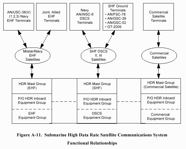
in multiple frequency bands using one HDR antenna group. Figure A-11 shows the relationship
of the submarine HDR system to other elements of the EHF and SHF communications
environment. Under the Submarine HDR SATCOM Program, a Joint Submarine
Communications Program Office (PMW 173) and Satellite Communications Program Office
(PMW 176) Integrated Products Team (IPT) will develop an SHF/EHF multiband antenna with
sufficient gain to provide a minimum SHF data rate of 128 kbps and a minimum EHF MDR data
rate of 64 kbps. The SHF/EHF multiband antenna design will permit future upgrades to attain
the data rates that have been identified by the Fleet to meet future requirements (256 to
1544 kbps). A dual band (SHF/EHF) transceiver will also be developed. This antenna will be
installed in all attack submarines (including potential SSGNs) and is under consideration for
SSBNs.
A.6.2 Ultra High Frequency Satellite Communications
The primary submarine UHF SATCOM upgrades are: (1) Mini-DAMA; and (2) TRE/
Commander�s Tactical Terminal (CTT). The DAMA time division multiple access (TDMA)
protocol provides improved interoperability and much more efficient use of the UHF satellite RF
spectrum. To achieve DAMA capability on SSNs as soon as possible, surface ship TD-1271
DAMA multiplexers have been and will continue to be installed (via TEMPALT) on deploying
SSNs. The second upgrade to SSN UHF capability is the installation of the TADIXS B
TRE/CTT, with IOC scheduled for FY96. Two TRE EDMs were installed during FY95 and are
under evaluation.
UHF SATCOM shore site modifications are also being pursued which will allow the submarine
force to continue to utilize the AN/BRT-6 Buoy once UHF Satellite has been fully upgraded to
support DAMA. A non-DAMA satellite channel will be required to allow the AN/BRT-6 to
remain functional into the next century.
In addition to Fleet Satellite (FLTSAT) UHF SATCOM, SSNs deployed to the polar region are
outfitted with the SAFS as a TEMPALT. The satellites which support SAFS are expected to
remain operational until approximately FY00. Beyond this timeframe, various SATCOM
alternatives are being explored that will provide connectivity to submarines. Interim possibilities
include an UHF Follow-On (UFO)/EHF (UFO/E) option.
A.6.3 Miniaturized Demand Assigned Multiple Access (AN/USC-42(V)1)
The Program Manager for Satellite Communications (PMW 176) is procuring the Mini-DAMA
(AN/USC-42(V)1) communications set (MDCS), which will replace the TD-1271 multiplexers
and AN/WSC-3 transceivers on submarines. In early FY95, PMW 176 re-directed the Mini-DAMA
program to an OSA, based on the VMEbus standard (IEEE 1014). Beginning in FY96,
two Mini-DAMA (AN/USC-42) EDMs will be evaluated on USS ALEXANDRIA (SSN 757).
Installation of production, OSA-based Mini-DAMA units will begin in FY96 and are scheduled
to be complete during the SARR Phase. Starting with IOC in FY96, a two channel OSA-based
Mini-DAMA capability will be installed on each SSN. Mini-DAMA will embed the protocol
and interface functions for OTCIXS II (DAMA OTCIXS), UHF SATCOM Advanced
Narrowband Digital Voice Terminal (ANDVT), and VINSON. It will also support three
embedded communications security (COMSEC) functions: (1) an IXS COMSEC, implementing
an embedded KG-84A for Mini-DAMA OTCIXS II data; (2) a Voice COMSEC, implementing
KYV-5 and KY-58 COMSEC for the embedded VOCODER; and (3) a Data COMSEC,
implementing KG-84A, KYV-5, and KY-58 data COMSEC functions. The Voice COMSEC can
also be configured by the operator as a second KG-84A. Both the Voice and Data COMSEC
functions are accessible via external RED I/O ports. The Mini-DAMA Voice and Data
COMSEC functions enhance submarine throughput by supplying additional, general-purpose
cryptographic devices (KG-84A).
An additional PMW 176 program, the GFCP II, will embed the functions of the ON-143(V)6,
including TADIXS A, non-DAMA Officer-in-Tactical Command Information Exchange System
(OTCIXS), and SSIXS. These embedded functions will replace existing legacy equipment. On
an SSN, the combined embedded functions of Mini-DAMA and one GFCP-II are equivalent to:
two KY-58s, two AN/WSC-3s, four TD-1271s and two ON-143(V)6s. The installation of this
modern, OSA-based equipment is an important milestone in the transition of the hybrid SCSS.
Installation of two channel Mini-DAMA (or equivalent) capability on TRIDENT is currently
planned to be deferred until installation of the TRIDENT SCSS ECS, scheduled for IOC in FY01
(FOC in FY06). To address the JCS DAMA mandate, PMW 173 will investigate options to
provide DAMA capabilities to the TRIDENT IRR prior to the SARR Phase (FY99).
A.6.4 Tactical Receive Equipment/Commander�s Tactical Terminal (CTT)
The TRE receives, decrypts, filters, formats, and transfers incoming Tactical Related
Applications (TRAP) Data Dissemination System (TDDS) and TADIXS B data to various local
baseband tactical data processors (TDPs) and printers for final processing. In addition to TDDS
and TADIXS B, the CTT Hybrid Receiver (CTT H/R) also receives and processes the Tactical
Information Broadcast Service (TIBS); a follow-on to the CTT (CTT H/3) provides a TIBS
transmit capability. TDDS, TADIXS B, and TIBS are UHF SATCOM broadcasts designed to
meet the requirements for delivering time-critical national and theater-derived sensor information
to operational users deployed worldwide (e.g., Over-the-Horizon Targeting (OTH-T)/
TOMAHAWK weapon target changes). TRE EDMs, fabricated and tested by NRaD San Diego,
are currently fielded, and are cross-decked to support operational requirements. Production TRE
terminals are currently in First Article Testing, with planned deliveries starting in FY96. To
comply with Congressional and DOD Inspector General (IG) direction, the Navy is procuring
some CTTs, as a follow-on to the Production TRE, while the services migrate to a Joint tactical
intelligence receiver, the Joint Tactical Terminal (JTT), planned for FY98 and beyond.
A.6.5 Generic Front-End Control Processor
PMW 176 is procuring the GFCP, which replaced the SIU on 688 class SSNs and provides the
interface between SCSS, the CCS, and the JMCIS TAC-3/4. The GFCP, based on the OSA
VMEbus standard (IEEE 1014), supports flexible I/O control and protocol conversion between
Interface Design Specifications (IDS) 8648 and IDS 8649. GFCP IOC occurred in FY94 and
GFCP is an element of the CY95 SCSS Prototype. As a funded P 3 I, GFCP II (ON-143(V)14)
will host several functions of the ON-143(V)6, including TADIXS A and OTCIXS. The
inclusion of SSIXS capability is a PMW 176 goal and would allow removal of the legacy, closed
system ON-143(V)6 units. GFCP II IOC is anticipated in FY96. GFCP capabilities are not
currently required nor planned for TRIDENT ECS.
A.6.6 Navy EHF SATCOM Program AN/USC-38(V)
The NESP will provide the following communication capabilities : joint interoperability, robust
anti-jam communication, low probability detection/interception, near global coverage, and
enhanced data rates when compared to existing UHF satellite communication systems. The
Navy EHF satellite system is comprised of two Fleet Satellites (FLTSAT 7 & 8) and will be
augmented by the Navy UFO satellites which will have EHF packages. Navy UFO satellites
began launching in December 1994 and will consist of a six satellite constellation when
completed. Additionally, the joint service Milstar satellite communication program will be EHF
capable when fielded and will be the primary EHF connectivity link for all the services.
The Submarine force is an integral part of the overall Navy EHF SATCOM Program with
45 NESP shipboard terminals, AN/USC-38(V), already procured for SSN/SSBN use by
N6/PMW 176. Until the submarine High Data Rate antennas are delivered, Type 8 Mod 3
periscopes are being modified with antennas to receive the EHF radio signal. Present EHF
shipboard terminals are LDR capable, upgradable to MDR.
Submarine EHF system testing to date has successfully demonstrated secure voice and secure
data transfers. When fully fielded, the EHF satellite program will provide a robust, covert, high
throughput tactical and strategic communication capability.
A.6.7 High Frequency Receiver/Transmitter Upgrades
Current R-1051 (SSN) and R-2108 (TRIDENT) HF Shipboard receivers are scheduled to be
replaced by R-2368A MF/HF shipboard receivers. The R-2368A also replaces the WRR-3 MF
receiver. No near-term replacement for the aging, legacy URT-23D HF transmitter has been
identified for submarines. The Navy HFRG and HF modernization program will be tracked to
ensure submarine requirements are supported. The IOC for HF modernization on destroyer-sized
combatants and smaller, and submarines, is planned for FY99. As a follow-on to HFRG
for modernization of HF radio suites on ships not scheduled to receive broadband HF Radio
Groups, the Navy is evaluating NDI, OSA based HF radio architectures for ships of all sizes.
This will include capabilities of high data rate HF (4800 bps and higher), Automatic Link
Establishment (ALE), HF e-mail and IP routing (i.e., the HF Channel Access Protocol [CAP] for
CSS), and rapid circuit set up and quick tuning. All ship classes traveling in a Battle Group will
be considered in the requirements. NDI, OSA-based HF transceivers and transmitters will be
investigated as part of the SCSS Prototyping efforts. As new HF equipment is fielded, the
function of legacy interface equipment, such as the URA-17, will be embedded and the legacy
equipment removed.
A.6.8 Maritime Cellular Information Exchange System
MCIXS, also described as Battle Group Cellular, uses COTS cellular telephony components to
support non-mission critical line-of-sight communications. MCIXS will be based on cellular
base stations, installed on the flagships of Battle Group Commanders, Amphibious Ready
Groups, and Fleet Commanders, and interfaced to a ship�s or submarine�s ECS, via a small
remote unit. This remote unit allows any desktop phone, fax, or modem to use the cellular
channels. COTS cellular telephones may also be used with the MCIXS. The MCIXS ORD is
being staffed for approval and includes MCIXS requirements for SSNs. PMW 173 will
coordinate with the MCIXS program to ensure that the SCSS ECS and SSN antennas can
support full cellular interoperability.
A.6.9 Improved Link-11
The Link-11 Improvement Program (LEIP) is designed to improve existing Link-11 high speed
computer-to-computer digital radio communications in the HF and UHF bands among NTDS
equipped ships, submarines, aircraft, and shore sites.
The LEIP is made up of three efforts: near term improvements to existing Link-11; U.S.
participation in the NATO Improved Link-11 (NILE) R & D program; and a U. S. companion
production program to the NILE research and development program, identified as Enhanced
Link-16 (EL-16). The near term program consists of: training initiatives; the development of a
low cost; light-weight, stand-alone Link-11 Display System (LEDS) for non-TDS units; software
upgrades to existing Link-11 Data Terminal Sets (DTS); the development of a Mobile Universal
Link-11 Translator System (MULTS); the acquisition of an NDI Link-11 DTS to replace old
units that are failing at an increasing rate; and the development of an Inter-American Naval
Conference (IANC) data link for operations with South American Navies. The NILE program
will produce a production specification and a reference system (testbed) against which each
nation�s privately developed Improved Link-11 system can be tested and certified. The
companion U.S. program is designed to take the NILE specifications into a competitive
procurement. Of these efforts, only the NILE development and the U.S. companion effort
continue in R&D beyond FY93.
A.6.10 VHF Special Operation Forces Communications
The purpose of VHF communications is to increase interoperability with SOF. Although HF and
UHF communications are used in the different aspects of SOF missions, two way VHF
communications is the method of choice for the insertion and recovery of SOF forces via the
submarine. The VHF frequency range is attractive because significant transmission distances
can be attained with minimal output power. In many insertion and recovery scenarios, the SOF
forces are located in hostile areas where active transmissions of significant power could allow
the enemy to determine the location of the SOF and lead to its capture. To complement the
inherent benefits of VHF communications (significant transmission distances for minimal output
power), some existing hand held VHF transceivers used by the SOF forces implement frequency
hopping algorithms to further prevent Directional Finding (DF).
In current SOF operations involving communications with submarines, carry-on VHF
transceivers, compatible with the hand held SOF radios, are brought onto the submarine and
temporarily installed in either the control room or the radio room by the SOF forces since
submarine radio rooms do not have VHF transceivers. The radio antenna used for SOF VHF
communications aboard submarines is the Type 18 Periscope Sleeve Antenna. There is currently
no plan to procure or install VHF transceiver radio equipment on submarines as a permanent part
of the SCSS. The program plan is to design and install a standard set of radio room interfaces on
all SSN submarines which will allow interoperability with the carry-on SOF radio equipment.
Additionally, NUWC New London is exploring better VHF antenna assets for the submarine in
order to allow better performance than the Type 18 Periscope Sleeve antenna in the VHF
frequency range.
A.6.11 CONTROLLERS, PERIPHERALS, AND INTERFACES
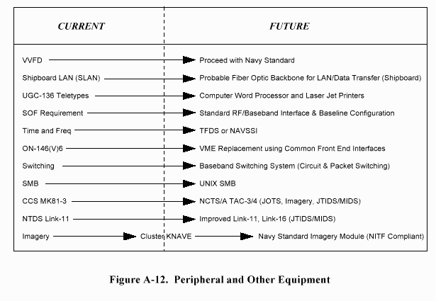
A summary of planned developments for peripherals and other equipment is shown in
Figure A-12.
A.6.11.1 Submarine Keyboard Printer (SKP - AN/UGC-136CX)
The AN/UGC-136CX upgrades the existing SKP (AN/UGC-AX) and provides a single line LED
display, larger buffer memory size, improved editing software, and automatic alphabet
conversion (for NATO VLF broadcast reception). The UGC-136CX also provides an additional
I/O interface port, which is used to connect the SMB to radio room traffic. The UGC-136CX
field change is underway for all 688 and TRIDENT class submarines and will be completed in
FY95. New construction submarines (688, SSN 21, and TRIDENT) will receive UGC-136CX
during construction.
A.6.11.2 Navy Standard Teleprinter
The Navy Standard Teleprinter (NST) program started in October 1989 to replace outdated and
insupportable Model 28 teletypes throughout the Fleet. The NST greatly enhances past
generation teleprinter capability with higher speed, greater storage, better reliability, and easier
maintenance. The procurement of NST teletypes has been completed and OPNAV (N61) is
addressing requirements for the follow-on generation of NSTs. Navy-wide feedback to date for
future teleprinter requirements are that computer word-processors and commercial printers will
satisfy all future needed capabilities. The program plan for submarine teleprinters is to transition
to these future capabilities from present UGC-136 series teleprinters.
A.6.11.3 Navy Tactical Command System - Afloat
Although not a radio room system, NTCS-A will be a primary user of the radio room
information streams and is an important system with which the SCSS must interface. Procured
by PD 70, the purpose of the NTCS-A is to provide a single, integrated Joint Command, Control,
and Intelligence system for all Navy platforms. NTCS-A supports all levels of command, from
each ship�s Commanding Officer/Tactical Action Officer to the Joint Component Naval
Commander to the Joint Task Force Commander. NTCS-A is transitioning to become a subset
of the JMCIS Common Operating Environment.
The NTCS-A program makes use of NDI hardware, i.e., the TAC-X workstation, as the standard
computer engine and COTS/GOTS software whenever feasible as the software engine. Program
plans for NTCS-A call for a Unified Build software release with modules capable of providing:
intelligence processing, imagery processing and display, an Afloat Correlation System (ACS),
access to the Naval Warfare Tactical Data Base, Automatic Electronic Intelligence, access and
display of Tailored Environmental Support System (TESS) data, automatic access and display of
Naval Tactical Display System (NTDS) information and various Warfare area specific tactical
decisions aids.
Fleet installations of fully capable submarine NTCS-A systems begin in FY94 on CCS Mk1
platforms. The submarine NTCS-A program will provide operators with contact track database
management functions on a TAC-3 computer workstation and will run with the Submarine Force
Mission Program Library (SFMPL). Both of these programs will be integrated for use with the
submarine Fire Control System (FCS). Interfaces for the radio communication circuits needed to
provide information for the submarine NTCS-A program will be provided through a GFCP
designed and tested by NUWC.
Submarine NTCS-A planned upgrades will provide 2-way Link-11, a SSIXS interface, and other
capabilities on CCS Mk2 platforms. Future submarine NTCS-A capabilities such as imagery
processing on the TAC-3 are in the evaluation and planning stages. Applicable, tailored portions
of the Fleet NTCS-A program will be continually assessed for use by the submarine NTCS-A
program based on fleet requirements.
A.6.11.4 Joint Tactical Information Distribution System
JTIDS is an advanced information distribution system that provides secure, integrated
communications, navigation, and identification (ICNI) capabilities for application to military
tactical users of all the services. JTIDS can be employed in most types of aircraft and surface
ships using either Class 1 terminals for large-scale airborne and surface command platforms or
Class 2 terminals for small, mobile, platforms.
JTIDS operates in the radio Air Navigation "L" frequency band and employs a TDMA technique
with a spread spectrum-frequency hopping waveform. JTIDS distributes encrypted information
at high rates with sufficient jam resistance to yield high reliability communications in a hostile
electromagnetic environment. The system has two navigation features: the TACAN function and
an integral position-location capability within a common reference grid. JTIDS has the
capability, through the secure dissemination of position information, to provide velocity and
identity data on both friendly and hostile force elements.
Historically, the terms JTIDS and Link-16 have often been used interchangeably, since the
JTIDS terminal is the principle component of Link-16. The Navy will initially be the principal
user of Link-16, using it to replace less capable Link-11 (TADIL-A) and Link-4A (TADIL-C)
data link systems.
A.6.11.5 Navy EHF Satellite Communications Controller
The NECC is one of the implementing programs of the CSS Architecture. The goal of the
NECC program is to provide communication services for the TDP users over the new EHF
SATCOM radios being implemented by the NESP. The NECC consists of a set of hardware and
software elements that will be implemented in two �Builds�. Build 1 is the development phase
and Build 2 is full scale production. Build 1 will provide the basic communication services to
support the IOC for the NESP terminals. The NECC will perform its mission by supplying
communications services to the users via a set of communications resources.
A.6.12 Cryptographic Devices and COMSEC Management System
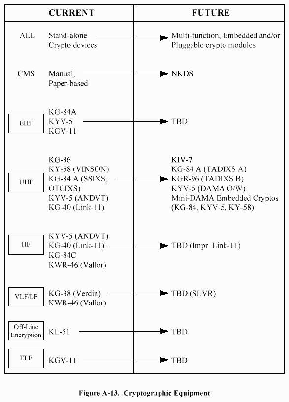
A summary of planned cryptographic equipment improvements is shown in Figure A-13.
A.6.12.1 Navy Key Distribution System
The purpose of the Navy Key Distribution System (NKDS) is to: reduce the quantity of paper
used in the Navy COMSEC Material System (CMS); reduce the administrative workload
performed by Fleet CMS Custodians and Users; and reduce the security vulnerabilities of the
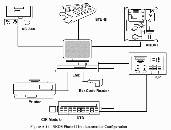
present CMS system. The NKDS fielding plan will be implemented during two phases and will
include: STU-III telephone, Local Management Device (LMD), Key Processor (KP), Data
Transport Device (DTD), Printer, Bar Code Device, KG-84C, and ANDVT.
Phase I will be implemented during FY94 and will provide administrative reporting capability to
the Director COMSEC Material System (DCMS) for destruction, accounting, and DCMS
bulletin board access. During this phase, only a STU-III telephone and an LMD (PC variant)
will be required.
Phase II will commence in FY97 and will allow the transfer of large quantities key material via
the STU-III telephone and LMD into the on-board Key Processor. On a case by case basis, the
system will allow Over-the-Air-Rekeying (OTAR) for an individual system key using the KG-84C
or ANDVT equipment. Figure A-14 is a block diagram of the NKDS Phase II
implementation.
The Submarine Force is participating fully in the NKDS program for both SSBNs and SSNs.
NSA and the Navy staff are examining backup alternatives that can be used by Navy platforms
to carry crypto key variables.
A.6.13 Submarine Imagery
The only operational submarine-based imagery system in use by the fleet today is the Cluster
Knave imagery system developed by the Office of Naval Intelligence. It is used by submarines
during tactical deployments and development of special tactical applications. Cluster Knave is a Macintosh-based image capture and processing system which uses the ANDVT for data
transmission via low gain, limited RF bandwidth, noisy communication channels while
minimizing transmission times. As part of the program plan, NUWC New London is working to
port existing Cluster Knave system capabilities into the TAC-3 computer workstation. Future
plans are to produce a unit that can communicate directly with Unified Build imagery module or
the Joint Deployable Intelligence Support System (JDISS).
A.6.14 Submarine Local Area Network
A Submarine LAN will be an additional system with which the SCSS must interface. NAVSEA
intends to implement shipboard LANs under the Integrated Interior Communications and Control
((IC)2 ) and SNAP programs. The SCSS must be able to interface with this ship-wide LAN. In a
NAVSEA letter (Ser PMS335/7899 dated 14 July 1993), Standard NTCSS-C4I Local Area
Network Backbone Architecture, PMS 335 and PMW 164 defined an implementation plan for
shipboard command and control systems. Although this architecture does not include combat
and weapons system requirements, it will be used for command and control systems to which the
SCSS must interface. The joint NAVSEA/SPAWAR implementation plan calls for installation
of a multi-mode fiber based LAN, using the Ethernet (IEEE 802.3) data link layer protocols and
redundant, commercial-grade fiber cabling. Separate classified and unclassified LANs will be
installed; Top Secret and SCI data will not be supported. This architecture provides an
immediate capability (10 Mbps) with a defined growth path to Fiber-Optic Distributed Data
Interface (FDDI) and ATM as requirements for these higher data rate services emerge. The
SCSS will support, as a minimum requirement, the ability to interface to this C2 LAN, and use of
this LAN for intra-SCSS data flows will be evaluated. During the SCSS Prototype, a shipboard
LAN and possible security products will be evaluated.
A.7 SUBMARINE COMMUNICATIONS EXPLORATORY DEVELOPMENT
PROGRAM
The following exploratory development submarine C 4 I research efforts are either in progress or
planned.
A.7.1 Advanced Research Projects Agency Funded Research
A.7.1.1 Advanced Technologies for Submarines Operating in the Littoral
The Naval Undersea Warfare Center Division Newport (NUWC DIV NPT) and the JHU/APL
are working with the Advanced Research Projects Agency (ARPA) on Advanced Technologies
for Submarines Operations in the Littoral (ATSOL). This program was established to identify
technologies that would support submarine littoral operations. The time frame for these
technologies investigations is circa 2015.
A major part of the ATSOL program focuses on identifying and developing advanced
technology communication systems for submarine surface operations in the littoral. To address
the ATSOL program, the communications team is performing the following:
- Considering antenna technologies determined to be high risk (including the evaluation
of currently targeted technologies for higher performance);
- Performing a broad sweep of industry to solicit innovative ideas (given the more
ambitious goals);
- Researching commercial communications trends;
- Exploring multifunctionality (e.g., shared apertures for communications, electronic
support measures (ESM), radar, and imaging);
- Providing a high priority to signature control;
- Investigating integration of the antennas into the ATSOL sail; and
- Unmanned Aerial Vehicle (UAV) connectivity to submarines.
A.7.1.2 Unmanned Aerial Vehicle
During FY96 a demonstration will be conducted to show interoperability and connectivity
between a UAV (Predator) and a SSN 688 class submarine. For this demonstration, a C-band
data link will be used between the UAV and the SSN 688 submarine using an antenna (Flat Top
Array and Horn Array) placed on top of the AN/BRD-7 mast. The ability to establish a video
link and control the flight pattern of all UAV by the submarine will be shown. Potential follow-on
UAV to submarine connectivity demonstrations being planned include evaluations using
UHF and Ku-band links of the radio frequency spectrum.
A.7.2 Exploratory Development (6.2)
The Submarine Communications Exploratory Development Program is managed by the
Submarine Electromagnetic Systems Department (Code 34) of the NUWC under sponsorship of
the Office of Naval Research, Science and Technology Directorate (ONR-ST Code 313). The
Submarine Communications Program is organized into two thrusts to support the requirements in
the Post-Soviet era: 1) provide robust, high data rate interoperable submarine communications
in all operational areas (Joint Interoperable High Data Rate Communications); and 2) improve
downlink communications at speed and depth (Communications at Speed and Depth).
The first thrust, Joint Interoperable High Data Rate Communications, includes the research in
submarine communications architectures to permit the submarine to participate in Navy and
Joint forces networks. It also provides a focus for the development and improvement of
submarine antennas which are needed to support this participation for the transfer of data at rates
that exceed the capabilities of existing submarine communications systems. This is an area of
increased emphasis.
The second thrust, Communications at Speed and Depth, includes the research needed to
improve antennas and systems that permit the transfer of information to submarines operating in
their speed/depth envelope below periscope depths. As a minimum, a one-way call-up system is
needed. Research is also supported to increase the data rate capability of low profile antennas
used to reach the surface from depth such as buoyant cable antennas. Emphasis on Arctic
Communications has been curtailed by terminating research in this area at the end of FY93.
For FY96 there are four projects within the Submarine Communications Exploratory
Development Program. These are:
- Low-Profile Submarine Communications Antenna,
- Open Architecture for Submarine Communications Networks,
- Submarine SHF Communications, and
- Submarine ELF Communications.
A.7.2.1 Low-Profile Submarine Communications Antenna
The Low Profile Submarine Communications Antenna Project addresses two of the four general
requirements for future submarine communications that were identified jointly by SUBLANT
and SUBPAC. These two requirements are: a) communications interoperability with the Joint
Task Force, and b) covert receipt of continuous record traffic. These requirements stem from
current restrictions in timeliness and data throughput of current communications available at
speed and depth. Certain modes of operation are currently not available, such as extended
transmission capability to a Task Force from a submarine at depth.
The objective of this project is to develop sustained 2-way UHF SATCOM capability for a
submarine at depth and to explore HF transmit capability while at depth. This project will
develop the appropriate antenna for UHF operation and will explore higher efficiency HF
antennas. As the feasibility of a capable HF-UHF antenna module for a buoyant cable antenna
(BCA) system becomes established, the implementation of accessory antenna functions, to
support early warning, GPS and cellular telephony, will be investigated. This project will also
develop the transmission line techniques to support the additional antennas, since the current
BCA leader cannot support UHF, and is very inefficient at HF. Planned future work will include
evaluation of techniques for higher frequency SATCOM operation and alternative antenna
configurations.
A.7.2.2 Open Architecture for SUBCOMMS Networks
The Open Architecture for SUBCOMMS Project addresses the open systems radio room and
communications network interoperability requirements for submarines.
The objective of this project is to use an open systems architecture radio room that incorporates
COTS/GOTS and other NDI products to the maximum extent possible and to develop techniques
that will maximize the submarine�s interoperability with communication networks.
Investigations of this project include the study of frame relay techniques (i.e., ATM, SONET)
and network performance assessments.
A.7.2.3 Submarine SHF Communications
The primary objective of this project is to identify and establish the feasibility of the
technologies that will allow implementation of HDR SATCOM with the submarine at periscope
depth.
A secondary objective of this project is to identify and implement an open systems approach to
submarine phased array communications antenna systems that allows the collocation of
additional electromagnetic capabilities such as ESM, radar, electronic countermeasures (ECM),
and millimeter wave imaging within the same aperture. A companion objective is to investigate
the feasibility of an integrated, communications-based �front end� electronics suite that can
support the additional, electromagnetic capabilities. This objective would accommodate
considerations of common processing and integrated platform data distribution.
A.7.2.4 Submarine ELF Communications
The Communications at Speed and Depth Project addresses two of the four general requirements
for future submarine communications that were identified jointly by SUBLANT and SUBPAC.
These two requirements are: a) communications interoperability with the Joint Task Force; and
b) covert receipt of continuous record traffic.
A second objective of this project is to develop the technology needed to demonstrate the
feasibility of a hull-mounted ELF antenna with steerable beam pattern, capable of surviving
maximum submarine speeds and depths and capable of providing reception down at several
hundred feet at operational speeds.


