 Introduction to
Naval Weapons Engineering
Introduction to
Naval Weapons EngineeringTracking Systems
The purpose of a tracking system is to determine the location
or direction of a target on a near-continuous basis. An ideal
tracking system would maintain contact and constantly update the
target's bearing (azimuth), range and elevation. The output of
the tracking system can be sent to a fire control system, which
stores the information and derives the target's motion and therefore
its future position. As we shall see, tracking systems not only
provide an automatic target following feature but also determine
the target's position with sufficient accuracy for weapons delivery.
Radar Servo Tracking System
One of the most basic tracking system designs is the servo
tracking system. Here, the radar antenna is initially trained
on a target after which it automatically remains pointed at the
target as it follows its motion. Furthermore, the system provides
continuous position information to the operator and possibly to
a fire control system. The antenna is rotated by a motor which
provides a negative position feedback signal to a controller.
This subsystem is known as a servo-mechanism.
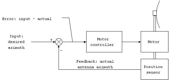
Figure 1. Servo mechanism
The commanded input signal is the desired azimuth of the antenna.
The error signal drives the motor to reposition the antenna until
the position feedback indicates the antenna is at the desired
azimuth, at which point the error signal is zero and the motor
stops. This servo-mechanism can be combined with a tracker,
which determines the azimuth a the target, which the system now
uses as the input.
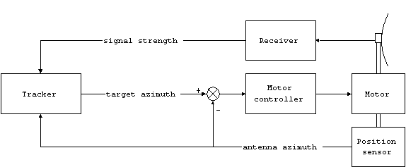
Figure 2. Servo tracking
mechanism.
This is the same servo-mechanism block diagram, but the input
comes from the tracker. The combination is called a radar servo-tracking
system. The heart of this system is the tracker, which takes
the return signal and position information and determines the
location of the target. There are several ways to do this, with
varying degrees of complexity and accuracy.
Consider the following data which might be obtained as
a circular sweep radar panned across a target.
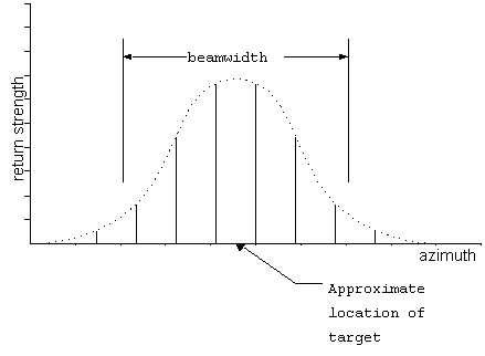
beam sweeps over target.
The individual returns are shown as the vertical lines. As the
beam sweeps across the target, there are eight returns generated,
whose strength increases until the target is centered in the beam
and then falls off. The target location can be determined from
the point of maximum return strength. However, the region of
maximum return is broad and therefore the exact location of the
target cannot be determined with high accuracy. Certainly, one
could locate the target within some fraction of the beamwidth,
but using this system the tracking accuracy would not be much
better than about one-quarter of the beamwidth. This still would
be insufficient for weapons delivery.
The accuracy can be improved by using a dual-beam system.
The two beams are offset in angle by a small amount to either
side. The center between the beams is known as the boresight
axis.
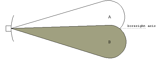
Figure 4. Dual beams.
The two beams can be created by a dual-feed system, where the
two parallel beams are fed into the reflector slightly to one
side or the other. When the beam is reflected, the offset in
the feed axis will cause the beam to be reflected off at an angle
relative to the boresight.
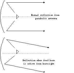
beam.
Now when a dual-beam system scans across a target, the return
will be the sum of the two beams. If one of the beams if inverted
(or made out-of-phase), the result will have a well-defined location
of the target, namely where the difference between the beams is
zero.
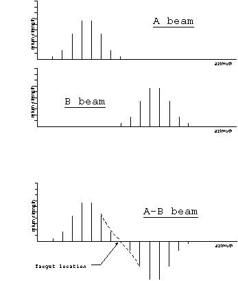
beam output.
Since the return strength is changing rapidly to either side,
the location of the target can be determined with great accuracy.
For a typical radar beam that is 30 wide, a dual-beam
system could track the target with 0.10 accuracy, which
is sufficient for weapons delivery.
Another nice feature of the dual-beam system is that the
return strength varies nearly linearly in the vicinity of the
target. Therefore it is easy to measure the target location even
if the boresight is not directly on the target. The difference
in target location and the boresight will be linearly proportional
to the return strength as long as the target is not too far off
center. Using the maximum strength method, it is not even clear
how to determine the correction direction to reposition the antenna,
since the return strength varies equally to either side of the
boresight.
The dual-beam system can also be used for tracking in
elevation. In fact, a monopulse system uses two dual-beam systems,
one for elevation and one for azimuth. This requires four beams
which are measured in pairs.
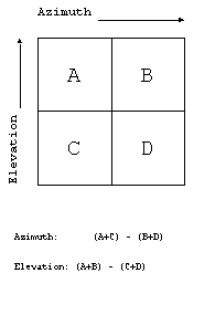
Dual-beam systems are generally used for fire control tracking,
where high accuracy is required. A dual beam system has a limited
range because the target is not in the maximum power portion of
the beam. The target is off-axis for either beam.
Range Tracking
Range tracking is accomplished in a similar manner to
dual-beam angle tracking. Once the range has been measured, the
tracking system attempts to predict the range on the next pulse.
This estimate becomes the reference to which the next measurement
will be compared. The comparison is made by using two range windows
called the early and late range gates.
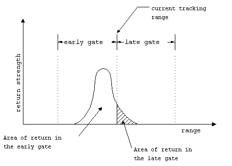
The area of the return in each gate is computed by integration.
The difference between the area in the early and late gates is
proportional to the error in the range estimate. If the two areas
are equal, the return is centered directly on the range estimate,
and there is no error. If the return has more area in the early
gate, the range estimate is too great, and therefore the range
error is positive. In the near vicinity of the range estimate,
there will be a linear relationship between the range error and
the difference in the areas.
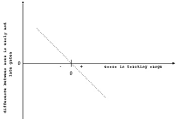
As long as the range estimate is not too far off, the tracking
error can be determined and the target range updated. Again,
like dual-beam tracking, the range tracking system can measure
the target range with greater accuracy than the range resolution
of the system, Rres, which is determined by the pulse
width and possibly the pulse compression ratio.
Track-while-scan (TWS)
In many cases, it would be undesirable to dedicate the
entire radar system to tracking a single target. We have already
seen that the servo tracking system maintains the antenna pointed
in the vicinity of the target at all times. Unfortunately, there
is no search capability when tracking using this method. The
track-while-scan (TWS) system maintains the search function, while
a computer performs the tracking functions. The TWS system is
capable of automatically tracking many targets simultaneously.
Furthermore, the TWS system can also perform a variety of other
automated functions, such as collision or close CPA warnings.
The TWS system manages targets using gates. We have already
seen an example of gates used in the range tracking system. A
TWS system may use range, angle, Doppler and elevation gates in
order to sort out targets from one another. When a target is
first detected, the computer will assign it an acquisition
gate, which has fixed boundaries of range and bearing (angle),
and possibly other parameters, depending on the system. When
the radar sweeps by the target again, if the return still falls
within the acquisition gate, the computer will initiate a track
on the target.
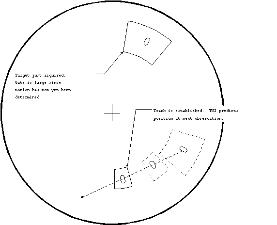
gates.
By following the history of the target positions, the course and
speed of the target can be found. The combination of range, bearing,
course and speed at any one time is known as the target's solution.
It is used to predict where the target will be at the next observation.
Once a solution has been determined, the computer uses a tracking
gate about its predicted position. If the target falls within
the predicted tracking gate, the computer will refine its solution
and continue tracking. If the target is not within the tracking
gate at the next observation, it will check to see if the target
is within a turning gate which surrounds the tracking gate.
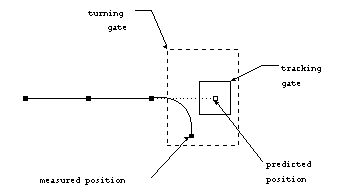
to maintain track on a maneuvering target.
The turning gate encompasses all the area that the target could
be in since the last observation. If the target is within the
turning gate, the computer starts over to obtain the new solution.
If the target falls outside of the turning gate, the track will
be lost. The system will continue to predict tracking gates in
case the target reappears. Depending on the system, the operator
may be required to drop the track.
The process of assigning observations with established
tracks is known as correlation. During each sweep, the
system will attempt to correlate all returns with existing tracks.
If the return cannot be correlated, it is assigned an acquisition
gate, and the process begins again. On some occasions, a new
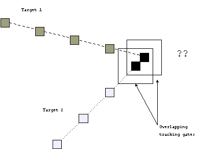
target may fall within an existing tracking gate. The system
will attempt to determine which return is the existing target
and which is the new target, but may fail to do so correctly.
It is common for TWS systems to have difficulty when there are
many targets, or when existing tracks cross each other. In the
later case, the computer may exchange the identity of the two
crossing tracks. In all these cases if mistaken identity, the
operator must intervene to correct the problem.
The TWS system uses a track file for each established target
that it tracks. The track file contains all of the observations
that are correlated with that particular target. For example,
the range, bearing and time of observation. The track file is
given a unique name known as the track designation. This
is usually either a simple number, like "track 25".
Depending on the system, the track file may contain other useful
information, such as the classification of the target, such as
"ship" or "aircraft". This information may
be used by the computer when determining the track and turning
gates. Finally, the track file also contains the current solution
to the tracks motion. Some systems maintain a history of solutions
which can be useful in determining the pattern of a maneuvering
target. For example, if a target alters course every 15 min,
such as a preset "zig" pattern.
Phased Array Tracking
We have already seen that a phased array radar system
can electronically steer the beam. But the system can also perform
a track-while-scan function. Since the planar array has many
independent elements, they need not all be used to form a single
beam. In fact, the great advantage of the phased array system
is its flexibility. The SPY-1 phased array radar has over 4,000
elements, any number of which may be combined into a single beam.
Suppose for instance, that the array was split into groups of
40 elements each. That would give about 100 independent beams.
Granted the beamwidth of the 40 element array would not be as
small as the 4000 element beam, but at shorter range could function
more than adequately.
In the phased array radar, some beams could be dedicated
to search functions, while other could perform dedicated tracking
functions. Therefore you have the search-while-track features,
but with the added benefit of continuous contact on the targets.
Essential to the SPY-1 capability is a computing system powerful
enough to perform all of the necessary functions to control more
than 100 independent tracking beams.
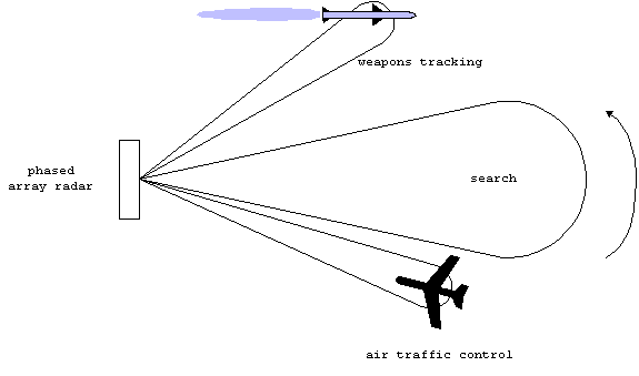
Figure 13. Multiple beams
of phased array radar.
Tracking Networks
It is a natural extension of the track-while-scan system
to create a system which shares tracking information between users.
All that is required is to transmit the contents of the track
file, since it contains all of the observations and the current
solution. The sharing of tracking information has been incorporated
extensively into modern combat. There are now global command
and control networks that share this information between users
all over the world.
Tracking networks have adopted a standardized set of symbols
for identifying types of targets. Some are shown below:
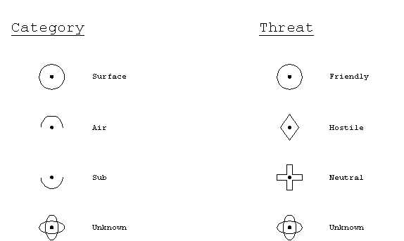
Figure 14. Some standard
tracking symbols.
These symbols appear on the common operational picture displays
now used for command and control functions.