
 Introduction to
Naval Weapons Engineering
Introduction to
Naval Weapons EngineeringBallistics
Interior Ballistics
When a projectile weapon, such as used in naval artillery,
is launched from the gun barrel, it is accelerated to a high velocity
by the burning of propellant. The propellant may travel with
the projectile or be stationary in the barrel. The gasses produced
by the burning propellant are trapped in the volume behind the
projectile. The introduction of more heat into the product gasses
causes the pressure to rise which in turn will accelerate the
projectile. On the other hand, the movement of the projectile
increases the volume which tends to drop the pressure.

are launched from a gun.
Initially, the pressure will rise, dominated
by the introduction of heat. As the projectile gains speed, the
expansion effect will get larger until a maximum pressure is reached.
Afterwards, the pressure will drop rapidly. The maximum, or
peak pressure determines how much stress the barrel must be designed
to withstand. Very large peak pressures require thick barrels.
Propellant Types
The exact shape of the pressure vs. position curve will
depend on how the propellant burns rate is controlled. The propellant
burns on its surface. If we take an ordinary shape for the propellant,
the surface area which is burning will decrease with time. This
is called a degressive propellant.

On the other hand, if the propellant is burned from the inside
as well as the outside, the net surface will stay the same, creating
a neutral propellant.

Lastly, the burn may proceed from many smaller interior positions,
in which case the propellant will be progressive:

Most propellant is not solid, but it comprised of many small pellets.
The shape of the individual pellets will determine the type of
burn rate. For cylindrical pellets the three types might look
like this:

Figure 5. Pellet type
propellant shapes.
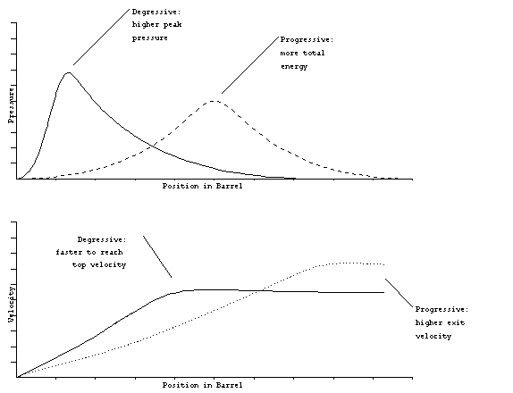
The type of propellant will alter the shape of the pressure vs.
position curve. Progressive pellets raise the pressure more slowly
than degressive propellants. For this reason, the peak pressure
is often less. On the other hand, degressive propellants accelerate
the projectile more rapidly in the initial portion of the barrel,
while progressive propellants can reach higher exit velocities.
A comparison of the two types is shown below:
propellants.
Which type of propellant to use depends on the application.
If the barrel cannot be made very long, it is better to use a
degressive propellant to achieve the maximum exit velocity in
a limited distance. An example might be a cannon on an aircraft.
As a consequence, however the barrel must be thicker to withstand
the increased peak pressure. If length is not restricted, a progressive
propellant can be used to minimize stress and achieve the maximum
exit velocity. An example might be a gun on a ship or tank.
Rifling
Most of the projectiles are spun as they travel down the
barrel. The barrel usually has rifling, which is either and indentation
or projection that twists around the barrel along its length.
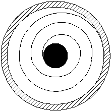
If the projectile is soft, like a bullet, the rifling digs into
the bullet to engage it. If the projectile is hard, it must have
projections on it which fit into the grooves on the barrel. For
naval ammunition, this is found on the rotating band, which also
serves to seal the volume behind the projectile so that propellant
gasses cannot escape. Here is the architecture of a typical projectile:
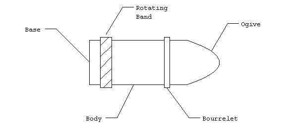
The parts function as follows:
Ogive - provides a protective cover with an aerodynamic shape.
Bourrelet - centers the projectile while minimizing the surface
area in contact with the barrel to reduce friction.
Body - contains the warhead.
Rotating Band - engages the rifling and seals the volume behind
the projectile to contain the propellant gasses. The rotating
band also centers the projectile like the bourrelet.
Base - provides a flat surface for the expanding gasses to push
on and accelerate the projectile down the barrel. The base may
also contain a firing mechanism to ingite the propellant if self-contained.
Exterior Ballistics
Gravity
Once the projectile leaves the muzzle (the end of the
barrel) its trajectory is governed many forces. Primarily, gravity
exerts a constant pull on the body and acts through the center
of gravity (CG) which is determined by the distribution of weight
throughout the body. Gravity always produces a uniform vertical
acceleration of about 9.8 m/s2.
Aerodynamic Forces
Next we have aerodynamic forces which provide lift and drag the
body as it flies through the air.
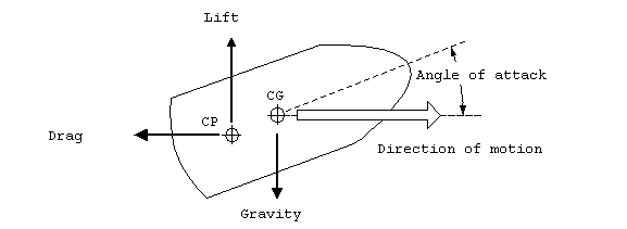
Figure 9. Aerodynamic
forces.
Aerodynamic forces are generally proportional to the velocity
squared. The aerodynamic forces act through the center of pressure
(CP) which is a function of the body's shape.
There are three types of drag force which apply to projectiles:
1. Skin drag- friction on the outer surface as it moves
through the air
2. Shape drag- caused by low pressure behind the body
due to the flow of air around its shape.
3. Wave drag - a loss of energy that is put into acoustic
waves as the body passes through the air. Particularly strong
near the speed of sound in air.
All drag forces act at the center of pressure and are in the opposite
direction as the motion of the projectile. The drag force can
be written as
Fdrag = CD(a)
A ½ rv2
where:
CD(a)= the coefficient of
drag, which is a function of the angle of attack, a;
A = the effective area of the body ;
r = the density of air (~1.2 Kg/m3); and
v = the velocity of the body relative to the air stream.
The lift force acts perpendicular to the direction of
motion relative to the air stream. It has the same form as drag
Flift = CL(a)
A ½ rv2
where: CL(a) = the coefficient
of lift, which is a function of the angle of attack, a.
Aerodynamic Stability
If the center of pressure is located behind the center
of gravity, when the body changes its angle of attack, the aerodynamic
forces create a restoring torque which tend to drive the body
back to its neutral angle, where all the torques are balanced.
This situation is therefore inherently stable, since the body
will always be driven back to neutral angle.

Figure 10. Flight stability.
The situation can be improved further by spin stabilization.
When the body is rapidly rotating about its principle axis, the
action of aerodynamic torque is altered. Instead of changing
the angle of attack, the same torque will act at a right angle
and change the yaw angle. Furthermore, the amount of deflection
will be reduced proportionally to the amount of spin. If the
body id spinning very rapidly, the amount of deflection will be
very small and the body will require a large amount of torque
to alter its orientation in any direction. The spin is achieved
by the rifling inside of the barrel.
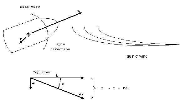
Figure 11. Spin stabilization.
Suppose a gust of wind tries to increase the angle of attack by
applying a torque T for a short duration of time, Dt.
The torque will change the angular momentum, L , by an amount
TDt. Recall that the angular momentum
,
L = Iw,
where:
I= the moment of inertia, and
w = the angular velocity (rotation
rate).
The additional angular momentum will be at a right angle to the
previous angular momentum. As seen from the top, the projectile
will deflect by an angle f. For small
deflection this angle can be approximated by
f TDt/Iw.
From this form, it should be apparent that the amount of deflection
can be reducing proportionally to how fast the projectile is spinning
about its principle axis.
Drift
Projectiles which are spin stabilized, are subject to
another force called drift. This is the same force that deflects
a "curve ball" in baseball. As the projectile moves
vertically, up initially then back down under the influence of
gravity, the spinning will tend to deflect the projectile perpendicularly
to the motion.
Coriolis Force
Projectiles which travel great distances are subject to
the Coriolis force. This is a artifact of the earth's rotation.
The local frame of reference (north, east, south and west) must
rotate as the earth does. The amount of rotation, also known
as the earth rate is dependent on the latitude:
earth rate = (2p radians)/(24 hours)
sin(latitude).
For example, at 30o N, the earth rate is 0.13 radians/hr
(3.6 x 10⁻⁵ rad/sec).
As the frame of reference moves under the projectile which
is traveling in a straight line, it appears to be deflected in
a direction opposite to the rotation of the frame of reference.
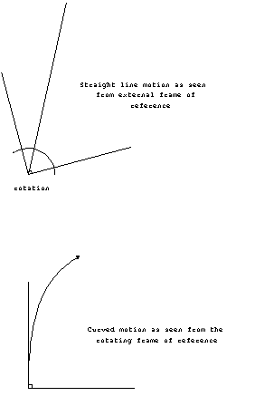
In the northern hemisphere, the trajectory will be deflected to
the right. A projectile traveling 1000 m/s due north at latitude
30o N would be accelerated to the right at 0.07 m/s2.
For a 30 second time-of-flight, corresponding to about 30 km
total distance traveled, the projectile would be deflected by
about 60 m. So for long range artillery, the Coriolis correction
is quite important. On the other hand, for bullets and water
going down the drain, it is insignificant!
Aiming Errors
When launching ballistic projectiles, an error in the
initial direction of flight will cause a significant change in
the location of the projectile at the end of its flight. The
longer the range, the greater the error. Suppose the aim is off
by some small angle, q, then after
traveling a distance R, the change in the position, Dx,
will be approximately
Dx Rq
Aiming errors can be caused by many things. First
of all, it is important to align the barrel of the gun with the
direction it is aimed. In aircraft, this is called boresighting,
where the gun barrel is aligned with the principle axis of the
aircraft. More commonly, the aiming device is aligned with the
gun barrel, called sighting.
Another type of error occurs when the aiming device is
separated from the gun barrel by a significant distance. This
creates parallax which can be corrected for, but only if
the range is accurately known.