 Introduction to
Naval Weapons Engineering
ASW Systems

Anti-submarine warfare (ASW) usually, but not always, involves
the use of sonar. Although the vagaries of the environment make
it difficult to predict and use, there is no other type of energy
propagation that travels so far in the ocean without significant
losses as acoustics waves. In this section, we describe the principles
of operation of the major types of sonar systems and one non-acoustic
system (MAD). We begin with the system that most closely resembles
the operation of basic radar, namely active sonar.
Active Sonar
A functional diagram of an active sonar system looks like this:

Figure 1. Active
sonar System.
The functional components are described below:
Transmitter. The transmitter generates the outgoing pulse.
It determines pulse width, PRF, modulation (optional), and carrier
frequency. The output power can be controlled by the operator.
The source level may be limited for several reasons. If the transducers
are driven with too much power, they can cavitate (drop the pressure
so low that the water boils). This is called quenching, and
it can destroy the transducer since the normal backpressure is
removed when bubbles form on its surface. Since the normal restoring
force is gone, the surface of the transducer can travel too far
(over-range) and damage itself. The quenching power limit increases
with depth due to the increased ambient pressure.
Another common phenomenon that limits the maximum source
level is reverberation, which is an echo from the immediate
surrounding volume of water. The reverberation level (RL) increases
with the source level (SL). At some point the reverberation exceeds
the noise level (NL) and will dominate the return signal. Since
reverberation always comes back from the same direction you are
projecting, the reduction in background noise, quantified by the
directivity index (DI) does not apply. When
RL > NL - DI,
the system is said to be reverberation-limited. The figure
of merit equation must be modified to reflect this:
FOMactive (reverberation-limited) = SL + TS - RL -
DT
When the system becomes reverberation-limited, the display will
begin to be dominated by noise near own ship in the direction
the active sonar is projecting. The solution is to reduce power
to just below the level at which reverberation-limiting occurred.
Transducer array. The individual transducers are simple
elements with little or no directionality. They are arranged in
an array to improve the directivity index, which improves the
figure-of-merit by noise reduction. The array of transducers reduces
the beamwidth in the horizontal (or azimuthal) direction, and
is usually circular in order to give more or less complete coverage,
with the exception of the region directly behind the array (where
the ship is). The array is protected from noise by own ship by
discontinuing the array in the after regions, and also by putting
in sound attenuating material. This region aft of a hull-mounted
array, from which the sonar system cannot detect is called the
baffles.
The array is also configured to reduce the beamwidth
in the vertical direction. Normally a hull-mounted array should
only receive sound from the downward direction, not directly ahead,
since the noise from the ocean's surface would destroy the sonar's
performance.
 Figure 2. Vertical beam of typical
cylindrical transducer array.
Beamforming processor. The input/output of each transducer
is put through a beamforming processor, which applies time
delays or phase shifts to each of the signals in such a way as
to create a narrow beam in a particular direction.
 Figure 3. Active beamforming.
The width of the beam formed by the beamforming processor will
determine the bearing accuracy of the system when searching.
In an identical manner to dual-beam tracking systems, sonar tracking
systems can improve on this accuracy tremendously, at the expense
of the signal-to-noise ratio.
4.) Duplexer. The duplexer performs the same function
in an active sonar as in a radar system, namely to protect the
receiver from the full transmitter power while the pulse is going
out. It can be thought of a switch that toggles between the transmitter
and receiver.
5.) Synchronizer. Performs same role as the synchronizer
in radar. Provides overall coordination and timing for the system.
Reset the display for each new pulse in order to make range measurements.
6.) Receiver. Collects the received energy. The receiver
compares the power level to noise with a threshold SNR (DT) in
order to determine if the signal will be displayed in a particular
beam. If the DT is set too low, there will many false alarms.
If it is too high, some detection capability will be lost.
The receiver may also demodulate the return if frequency modulation
is used on transmission. Sonar systems often use pulse compression
techniques to improve range resolution.
7.) Display. Puts all of the detection information into
a visual format. There are several types:
A-scan: the signal along a single beam for a portion of the listening
cycle. A target appears as a raised section if it is in the beam.
 Figure 4. A-scan display.
PPI: plan position indicator. A top-down (geographic view).
The sonar system must sequentially search individual beams which
are displayed in their true or relative form. The strength of
the return is represented by the intensity on the display.
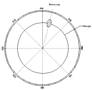 Figure 5. PPI display.
Passive Sonar Systems
The passive sonar system differs from the active system
in many regards. Below is a typical functional diagram:
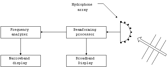
Figure 6. Passive sonar
system.
Hydrophone array. These are the sensitive elements which
detect the acoustic energy emitted from the target. Again, they
are arranged into an array to improve the beamwidth. Common configurations
are cylindrical or spherical. The cylindrical array operates at
a fixed vertical angle, usually downward. The spherical array,
which is common on submarines, has a much wider vertical field-of-view.
Since the submarine may be below what it is tracking, the array
must be able to look upwards to some extent. The large downward
angles are only used for bottom bounce detection. Using a beamforming
processor (described below) the field-of-view is broken down into
individual beams in the vertical and azimuthal directions.
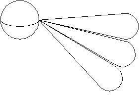 Figure 7. Spherical array showing
multiple vertical beams.
Beamforming processor. Unlike active systems which transmit
and receive in a set direction, the passive system must listen
to all angles at all times. This requires a very wide beamwidth.
At the same time, a narrow beamwidth is required for locating
the source and rejecting ambient noise. These two objectives are
achieved simultaneously by the passive beamforming processor.
The idea is very similar to the active system.
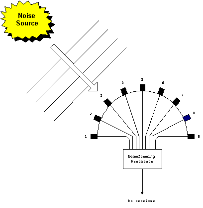 Figure 8. Passive hydrophone
array.
The passive beamforming processor applies a unique set of time
delays/phase shifts to the signal to create a particular beam.
The difference in a passive system is that this process is repeated
several times, each with a different set of time delays/phase
shifts, in order to listen to many narrow beams nearly simultaneously.
The result is a set of beams that cover the field-of-view of the
array.
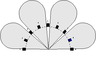 Figure 9. Passive beamforming.
The beams should not be thought of as coming from the individual
hydrophones. In fact, each of the beams so created has a narrow
beamwidth that comes from the full aperture of the array, not
the individual hydrophones.
Broadband display. The output of the beamforming processor
is displayed as a bearing time history (BTH):
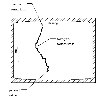 Figure 10. Bearing time history
(BTH) display.
The newest information is at the top of the display. The beamwidth
of the system determines how accurately the bearing can be measured
by such a display. A common beamwidth is about 5o.
The total amount of time displayed from top to bottom can be controlled
(to some extent). A quickly updating display that only kept information
for a few minutes would be useful for close contacts whose bearings
are changing rapidly. On the other hand, a long tie history is
more useful for detecting long range contacts, whose bearings
are only changing slowly.
4.) Frequency Analyzer. The frequency analyzer breaks
the signal into separate frequencies. This is the spectrum of
the signal. For processing purposes, the frequencies are divided
into small bands known as frequency bins. The width of
each bin is called the analysis bandwidth.
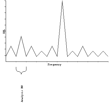 Figure 11. Frequency analysis.
Sonar systems can gain considerable signal-to-noise improvements
by matching the analysis bandwidth to the bandwidth of narrowband
sources. The way to illustrate this is by two counter examples.
If the signal processing bandwidth is too wide, then noise from
the part of the spectrum beyond the signal is let in and the SNR
is degraded. If the bandwidth is too narrow, then part of the
signal is excluded, also reducing the SNR. It should be obvious
now that the best situation occurs when the bandwidth exactly
matches the signal. This is possible when the characteristics
of the signal are well known, which they are for most targets.
The frequency analyzer separates (filters) the signal
into discrete bins, inside of which the SNR is maximized. The
frequency content of the signals from a target information provides
vital information about its identity and operation. These frequencies
are also subject to the Doppler shift, just like radar, are therefore
can provide information about the range rate. This requires that
the original frequency be known exactly, which is generally not
the case. However, many important facts can be inferred by the
changes in the received frequency over time.
Narrowband Display. For a particular beam, the time history of
the frequency is called a waterfall display.
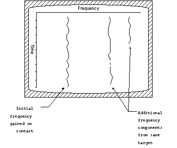 Figure 12. Waterfall display.
This can be used to gain additional information from a contact
which is already being tracked by another system. In order to
search for contacts on the basis of narrowband information alone
requires a different type of display. One possibility is to simultaneously
display several different beams, each showing a mini-waterfall
display, which are called grams.
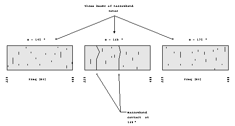 Figure 13. Narrowband grams.
These are quite useful, but require great concentration on the
part of the operator because there is more information displayed
at any one time. Many systems require the operator to systematically
search the entire field-of-view, looking at only a few beams at
a time.
Variable Depth Sonar (VDS)
Variable depth sonars use large transducers that are towed
from the ship on a cable with an adjustable scope. The combination
of the buoyancy, ship speed and cable scope determine at the depth
that the transducer will be at. VDS is used for two main reasons.
At increased depth, the source level (SL) can be increased
greatly, since the quenching limit is higher. This is due to
increased backpressure on the surface of the transducer. Secondly,
the VDS can be operated below the layer.
Recall that the combination of positive over negative sound velocity
profiles created a layer at the interface. The layer makes it
difficult to propagate sound across it. Therefore, ships using
hull-mounted sonar systems will be unable to detect submarines
operating below the layer, except possibly at short range. However,
if the VDS can be place below layer, the ship can take advantage
of the deep sound channel while being in the shadow zone of the
submarine's sonar.
Towed Array Sonar Systems (TASS)
A towed array is a linear array of hydrophones. The array
is towed behind the ship on a cable of variable scope like a VDS.
However, it is strictly a passive system.
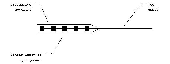 Figure 14. Towed array.
The signal from the array is led to a beamforming processor which
creates several narrow beams. Because the array is linear, there
is no vertical directionality. This causes two problems. The
first problem occurs when there is bottom bounce propagation.
In this case, the direction of the source is not known without
further analysis.
The second problem is an ambiguity in relative bearing.
The linear array cannot distinguish signals on the left from
those on the right.
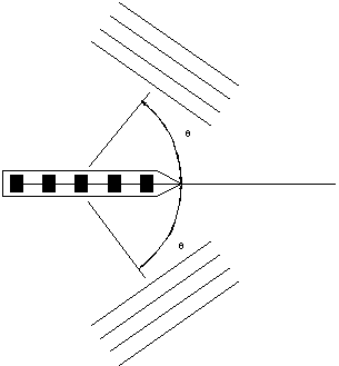 Figure 15. Bearing ambiguity
with towed array.
The problem of bearing ambiguity can be resolved by maneuvering
the ship. When contact is regained, there will again be two ambiguous
bearings, but only one of which will match the previous case (assuming
that the target hasn't moved much between legs).
Example: a towed array contact is gained at relative bearing
030/330 R, while the ship is on course 045 T. The ship changes
course to 135 T and regains the contact at 060/300 R. Find the
true bearing to the actual contact.
First leg: the contact is at either 015 T or 075 T (045 030).
Second leg: the contact is at either 075 T or 195 T (135 060)
Therefore the actual contact is at 075 T.
Because the array is not constrained by the size of the
ship, towed arrays can be made very long. Therefore, they have
very narrow beamwidths, or alternatively, can operate at much
lower frequencies. Low frequency capability is particularly advantageous
because there are many sources at low frequency, with large source
levels, and there is very little loss from absorption.
Sonobuoys
Sonobuoys are small, self-contained sonar systems. They
are dropped into the water by aircraft at which point they deploy
themselves. The information from the sonobuoy is transmitted
to the aircraft by VHF radio link. The information can also
be relayed to ships. Signal processing and analysis is performed
by equipment in the aircraft, or ship. After some period of operation,
the sonobuoy will scuttle itself.
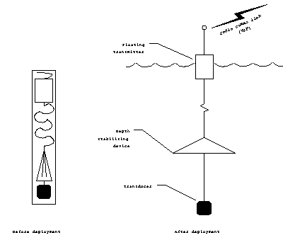 Figure 16. Sonobouy deployment.
There are many types of sonobuoys, depending on their capabilties:
DICASS: directional command activated sonobuoy system. Active
system which transmits pulses when commanded by the aircraft.
DIFAR: direction finding acoustic receiver. This is a passive
system, with some directionality achieved by a small hydrophone
array.
VLAD: vertical thin-line array. A linear, vertical array of
DIFAR hydrophones. Has improved directionality in vertical direction.
Reduces noise from surface.
Most sonobuoys can operate at several preset depth settings.
The shallow setting is used for surface duct propagation, and
the deep for sound channel propagation.
Sonobuoys have poor values of directivity index, mostly
because of their limited size. Figure-of-merit is not always
low, however, because sonobuoys also have very low self-noise.
Depending on the environment, and whether or not self-noise is
dominant, sonobuoys can actually outperform some larger hull-mounted
systems.
Bi-Static Sonar
This is a combination of an active system for transmission
at one location with a passive system for reception at another
location. 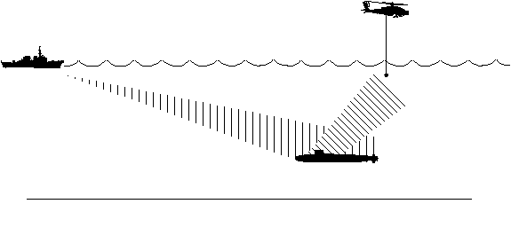
Figure
17. Bi-static sonar.
The passive system does not suffer from the same reverberation
limitations as the standard active system. The source level can
be very high (up to the quenching limit). Some system use explosive
driven projectors with incredible source levels. The source may
be well outside the weapons range of the target. Furthermore,
the transmission loss is less than the full two-way loss of normal
active. Sometimes the projector is a sonobuoy.
Non-Acoustic Detection
Visual
Submarines near the surface are very vulnerable to visual
detection. Anything that protrudes above the surface like a periscope,
antenna or mast will leave a significant wake if the submarine
is moving at any speed over a few knots. Since depth control
and steerage is very difficult at low speeds, it is not uncommon
for submarines to be at 4 or 5 knots just below the surface.
The mast will create a wake, called feather, which is
quite visible, and also leave a remnant of its passage, called
a scar. The scar is a long streak of foam or bubbles left
behind after the object passes. The feather may be a few meters,
and the scar tens of meters long. Either may be visible for up
to 10 miles, and are easily spotted by low flying aircraft in
the vicinity. If the water is especially clear, the hull may
be visible for a few hundred feet under water, but is usually
not distinguishable unless the water is shallow with a light colored
bottom (like white sand).
Radar
Exposed periscopes and masts can be detected by specially
designed radars. The radar cross section is very small and is
generally not detectable by ordinary radar systems. Furthermore,
the sea clutter near the target will generally obscure it. To
be effective against a periscope or mast, the radar should have
very small range and bearing resolution and must be vertically
polarized to match the structure of the target. ISAR has proven
to be very effective against submarine periscopes and masts.
Some special radar systems have demonstrated the capability
to detect the presence of a submarine by the change in the surface
water height as it passes, known as the bernoulli hump.
This effect is greatest when the submarine is shallow and moving
very fast. These are not real time assets however, since the
signal processing takes several hours to complete.
Infrared Detection
Submarines are vulnerable to infrared detection when they
are snorkeling, since the diesel exhaust is released close to
the surface (as it must be because of the backpressure limitation).
The exhaust gases give off a sufficiently strong infrared signature
as to be detectable. However, this is only useful if the submarine
is snorkeling, which it very infrequent for nuclear powered submarines,
and only a few hours a day for diesel-electric submarines.
Magnetic Anomaly Detection (MAD)
Magnetic anomaly detection systems, measure the change
in the earth's magnetic field due to the presence of a large amount
of ferrous material found in most submarines. The effect can
only be detected if the submarine is relatively shallow, and therefore
is not a great long range detection system. It can however,
provide a precise location of the submarine of sufficient accuracy
to permit weapons delivery, which is its main use.

 Introduction to
Naval Weapons Engineering
 Figure 2. Vertical beam of typical
 Figure 3. Active beamforming.
 Figure 4. A-scan display.
 Figure 5. PPI display.
 Figure 7. Spherical array showing
 Figure 8. Passive hydrophone
 Figure 9. Passive beamforming.
 Figure 10. Bearing time history
 Figure 11. Frequency analysis.
 Figure 12. Waterfall display.
 Figure 13. Narrowband grams.
 Figure 14. Towed array.
 Figure 15. Bearing ambiguity
 Figure 16. Sonobouy deployment.