 Introduction to
Naval Weapons Engineering
Introduction to
Naval Weapons EngineeringControl Systems Engineering

Open and Closed Loop Systems
The most fundamental concept for control systems engineering
is the block diagram. The simplest element of a block diagram
looks like this:

This is also a complete system by itself. This system takes
the input and generates output through the action of the plant.
The details of the internal workings of the plant are unspecified,
and to some extent irrelevant. All we are concerned with here
is the relationship between the input and output. A well-behaved
system might have the output proportional to the input, but it
needn't be so. Your stove top burner is an example. The input
is the control knob. You turn it to one of its settings, somewhere
between off and fully on. The plant is the burner itself, which
outputs heat. In this case the amount of heat is proportional
to the input.
A system which operates in this manner is known as an open-loop
system. This distinguishes it from another type known
as closed-loop systems.
These systems utilize feedback, which is derived from the output.
Here is a block diagram of a closed-loop system.

Continuing with the kitchen theme, your oven is a closed loop
system. You input the temperature you desire and the plant (oven)
outputs heat. As the oven heats up, the thermostat provides feedback
to the oven, which in turn reduces the heat output. Eventually,
steady-state is reached at the desired temperature. Now, it is
possible to make this system work with an open-loop system, but
the design engineer must have near-perfect knowledge of how much
heat output will sustain the desired operating temperature. If
he is inaccurate or something changes in the heat balance equation,
the oven will not operate at the desired temperature.
Here is a short comparison of the two fundamental types of
control systems:
Table 1. Comparison of open and closed loop control systems.
| open loop systems | closed loop systems |
| simple design | more accurate |
| accuracy depends on calibration | less sensitive to change in environment |
| unlikely to become unstable | smooth response |
| wider bandwidth | |
| can become unstable |
If we restrict ourselves to linear systems, then we may take
over a wide range of mathematics especially suited for these systems.
The technique uses the Laplace transform. The details are unimportant
for now, but it provides a great simplification. Let me explain
how.
First, suppose we have an electrical circuit. If we provide
input in the form of a voltage that varies with time, vin(t),then
typically the output vout(t)
is the solution to some complicated set of differential equations.
But if you convert the input and output into their Laplace transforms,
where
R(s) = {vin(t)} is the Laplace transform of the input, and
C(s) = {vout(t)}
is the Laplace transform of the output.
The new independent variable is "s", which can be
interpreted as the spatial frequency, with units of cycles/meter.
It is also possible to reverse the Laplace transform, therefore
recovering the output in its original form (i.e. voltage or current
as a function of time). For example -1{R(s)}
= vin(t).
Here is a short table of Laplace transform pairs for commonly
encountered functions:
Table 2. Laplace transform pairs.
| Time domain: f(t)= -1{F(s)} | Laplace domain: F(s) = {f(t)} |
| a (constant) | 1/s |
| at (ramp) | a/s2 |
| e-at (exponential) | 1/(s + a) |
| sin(at) | a/(s2 + a2) |
| cos(at) | s/(s2 + a2) |
The Transfer Function
For linear systems, the simple relationship between R(s) and
C(s):
C(s) = G(s) R(s)
where G(s) is known as the transfer
function. The transfer function can be determined from
detailed analysis of the plant, using differential equations.
So this method is not particularly simple if this were the only
problem to solve. The great simplification occurs when plants
are combined with other plants and feedback loops. If the transfer
function of each plant is known, then they may be combined using
ordinary algebraic methods instead of differential equations.
All that is required is to obtain the solution is to take the
inverse Laplace transform after all the manipulation is completed.
Its similar to reducing a complicated circuit in to an equivalent
impedance and voltage (Thevenin equivalent).
The method can be summarized in steps:
Change variables from time "t" to spatial frequency "s" using the Laplace transform.
Algebraically manipulate combinations of transfer functions to find the relationship between the input and output (i.e. a single transfer function).
Compute the output in s.
Change back to the original variable t using the inverse Laplace
transform.
Let's see this in action on a closed-loop system. All the
signals are now represented as functions of the new variable s.

Figure 3 . Closed loop system in Laplace domain.
Here, we have two elements, the plant with transfer function,
G, and feedback transfer function, H. The action of the summing
junction is to subtract the feedback signal B(s) from the input
R(s) with the result known as the error signal, E(s) = R(s) -
B(s).
We exploit the properties of Laplace transforms and write
the following relationships:
C(s) = G(s) E(s)
E(s) = R(s) - B(s)
B(s) = H(s) C(s)
If we want to know the relationship between the output and
the input (and who wouldn't?) we eliminate the extra variable.
C = G E
= G(R-B)
= G(R - HC)
C(1+GH) = GR
C/R = G/(1+GH)
Again we have a relatively simple relationship between the
input and the output. In fact the term G/(1+GH) is also a transfer
function for the closed-loop system. If we were to give a separate
label like CLTF (closed-loop transfer function), then
C(s) = CLTF(s)R(s)
This process is known as block reduction. It turns out that it is always possible to reduce a complication block diagram into a single transfer function. If you were to analyze some complicated weapons system of computers and hardware, eventually you could (theoretically) reduce its operation to a few transfer functions which connect the input variables to the output variables.
This is the reverse process of the systems approach where
large projects are divided into smaller ones. We would expect
it to work both ways of course. When learning how things work
it is always better to start with the big picture and then focus
on the details as they become important.
System Response
Since the majority of control systems used in weapons are
closed-loop systems, we now consider how a generic system will
respond to a step change in the input. An example might be a missile
on a heading of 330o
responding to a new input course of 270o.
How the system responds will depend on the exact nature of the
transfer function. There are three main ways in which the system
can respond:
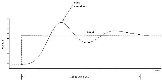
Under-damped response. The system will change the output quickly
to the new value but in the process will overshoot the desired
output. The output will settle into the new value after one or
more oscillations. If we plot the response, it might look like:

The output will always overshoot the desired output, and the
maximum value is called the peak
overshoot. When the output oscillates (goes above and
below the final value at least once), the systems is considered
to be under-damped. The length of time it takes the system to
reach its final value is called the settling
time.
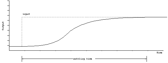
Over-damped. In this case, the response is quite slow. The output will sluggishly approach its final value and there will be no overshoot.

Figure 5. Response of over-damped system.
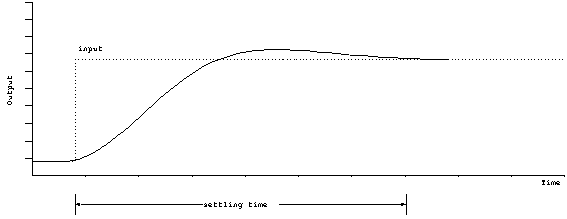
Critically damped. This is the dividing line between over and under damping. Critically damping may or may not overshoot the final value, but there will be no oscillation. Critical damping reaches it final value in the minimum amount of time. There is only a small range of parameters which will achieve critical damping, and therefore it is rarely achieved. Critical damping should be thought of as an idealized situation that differentiates between over and under damping.

Figure 6. Response of critically damped system.
It is not always clear that the system should be designed
to be critically damped, it depends on the application. For instance,
if the system cannot tolerate any overshoot whatsoever, it would
be wise to make the system slightly over-damped. On the other
hand, if the input is constantly changing, and the quickest initial
response is needed, then the system should be slightly under-damped.
Example: How do you classify the shock absorbing system on
a car?
When the shocks are new, the car will respond quickly to a
step change in input (i.e. a bump in the road). The car will usually
overshoot and may or may not oscillate. The system is probably
just slightly under-damped.
As the shocks age, the dampers wear out, and the system will
become more under-damped. When a bump is encountered, the car
will oscillate a few cycles before settling down.