
 Introduction to
Naval Weapons Engineering
Introduction to
Naval Weapons EngineeringNavigation for Weapons

Global Position System
Principle of Operation
GPS is a satellite based navigation system. It uses a
digital signal at about 1.5 GHz from each satellite to send data
to the receiver. The receiver can then deduce its exact range
from the satellite, as well as the geographic position (GP) of
the satellite. The GP is the location on the Earth directly below
the satellite. This establishes a line of position (LOP) on the
Earth, as illustrated in figure 1.

on the surface of the Earth from
a single satellite.
A second LOP will provide for two possible locations, as shown
in figure 2., and a third LOP will resolve that to a single position
on the Earth.

of position on surface of Earth (2-D mode).
The range from the satellite is determined by the time the signal
is received. The satellite signal includes the time at which
it was sent. By comparing that to the receiver clock, the time
delay and hence the range can be determined. The satellites contain
precise atomic clocks and are updated from the master station.
On the other hand, you typical inexpensive GPS receiver does
not contain a precise atomic clock. However, the signal from
a fourth satellite can be used to solve for any error in the receiver's
clock. As a result, the receiver obtains an accurate navigational
fix, including altitude, as well as a precise clock update.
In order for the system to work, there must be at least
four satellites visible to the receiver at all times. In fact
there are 21 operational satellites, and three spares, in orbit
at about 20,000 km, which circle the globe every twelve hours.
A rough calculation will show this to be sufficient.
Assume 21 satellites, evenly spaced over the 4p
steradians of the Earth's sphere. That gives about 4p/21
= 0.6 steradians per satellite. If you can see about
¼ of the sky at any one time, that would be p
steradians, which would involve p/0.6
5 satellites on average.
System Components
The basic system is divided into three segments:

Figure 3. Segments of
GPS.
Spaced-based segment
The space-based segment consists of the 24 satellites. They travel
on polar orbits around the Earth once every twelve hours at an
altitude of about 20,000 km. The position directly beneath the
satellite is called its geographic position. For a polar orbit
the geographic position travels roughly along a particular meridian.

Figure 4. Polar orbit.
The orbits of the various satellites are spaced at 55o
intervals. A typical satellite is shown below.
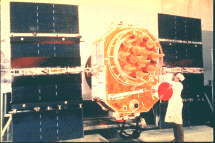
Figure 5. GPS satellite.
Control segment
The master control station (MCS)is in Colorado Springs, and run
by the Air Force. There are also five unmanned stations in Hawaii,
Kwajalein, Diego Garcia, and Colorado, which track the satellites
and relay information to the MCS. There are three uplink antennas
at Diego Gargcia, Kwajelein and Ascension.
The control segment tracks the satellites and updates their orbital
parameters and clocks.
User segments
These are the GPS receivers. They receive the satellite
transmissions and perform calculations to determine the position,
altitude and time outputs. The antenna is designed to receive
the circularly polarized satellite signal at either 1575.42 (L1)
or 1227.60 (L2) MHz. The difference between these signals will
be discussed below. The signal is basically comprised of a 50
bps bi-polar phase shift keyed (BPSK) digital signal containing
the navigation data, which is carried on a 1,023 MHz spread spectrum
signal which serves two purposes:
To encode the identity of the satellite.
To widen the signal bandwidth which reduces the threat of interference from narrowband sources.
Performance
The GPS system is accurate to within of about 53 ft. in
position, 0.3 fps in velocity and 100 nsec in time. However,
for the purpose of denying a precise navigational system to possible
hostile forces, a random error of anywhere between 130 and 330
feet is intentionally inserted. The degraded signal is used in
the Standard Postioning System (SPS). The unadulterated signal
is known as the PPS (precise positioning system) and is only
available to government approved users. The PPS requires decryption
to be useable.
To compensate for the injected errors, a system has been
developed, outside of the government program, to measure and correct
for the error. This is known as Differential GPS or DGPS. The
principle of operation is that a fixed site, with well-known position,
obtains a SPS fix, measures the error and broadcasts the correction
to other DGPS users.
Applications
For any extended range weapon system, precise and continuous
positioning information is invaluable. GPS using PPS can be expected
to be used in all platforms, missiles, guided projectiles, sonobouys,
etc…
Inertial Navigation Systems
Principle of Operation
Inertial navigation is based on the concept of calculating
the difference in position from some reference point based on
the measured acceleration at frequent intervals. For simplicity,
consider a one-dimensional case like the distance a train moves
down the track. Suppose the train is initially moving with velocity,
v0. If we consider a short time interval, Dt,
the train will move a distance of x = v0Dt
during that period. If there is no acceleration, the total distance
covered could be found similarly for any time interval.
If the train accelerates, perhaps by an increase in the
throttle position, the velocity will begin to change. An algorithm
could be set up to compute the distance traveled by iteration:
x = x0
v = v0
step 1: x = x + v Dt
step 2: measure a
step 3: v = v + a Dt
step 4: repeat step 1
Such a procedure could easily be carried out by a computer.
All that is required is a means to measure the acceleration at
any time. A device that does this is called an accelerometer.
The simplest design is nothing more than a mass, m, on a spring,
oriented in the direction of motion, with a scale that measures
the compression of the spring.
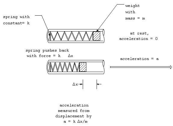
Figure 6. Accelerometer.
The acceleration will cause the spring to compress until the force
of the matches the mass times the acceleration (recall that F
= ma). The force of a spring is linear with the change in the
length of the spring, Dx, which can
be written as F = kDx, where k is the
spring constant. Be measuring the change in length of the spring,
the acceleration can be calculated by:
a = kDx/m.
This design can be extended to more degrees of freedom. Ultimately
we need three degrees of freedom. We would need to have three
accelerometers, one for each direction. Unfortunately, when the
object changes directions, the accelerometers mounted on it, will
change direction relative to an external frame of reference. In
fact the coordinate systems used should ideally be an inertial
frame of reference, meaning that it is not accelerating. For
navigation, it is tempting to reference some Earth-based coordinate
system like latitude and longitude. However this system is non-inertial,
because of its rotation. In fact, any point on the surface of
the Earth must be accelerating inward at 0.03 m/s2
to stay in position. Fortunately, this can easily be accomplished
by gravity. A proper reference system can be Earth-based, with
one of its axes aligned parallel to the axis of the Earth for
example, but it cannot rotate. For this reason, many inertial
frames are chosen based on the stars, called celestial frames.
Having chosen a proper inertial reference frame,
we need to know the orientation of our object relative to the
inertial frame. Then the measurements from the accelerometers
can be transformed into the reference frame. After this, the
previous procedure may be carried out. Perhaps the simplest way
to achieve this is create a perfect gimbal system which keeps
the accelerometers always oriented with the reference frame and
lets the object move around it. Of course, this isn't possible
with mechanical systems, due to friction. Early systems used
a complicated system of gyroscopes to maintain the orientation.
This system is known as the stable platform. It provides the
proper orientation for the accelerometers at all times, regardless
of the motion of the object to which it is mounted.
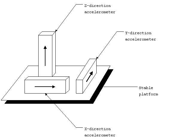
Figure 7. Inertial navigation
system (INS).
We will discuss ways to maintain or keep track of the orientation
of the accelerometers relative to the inertial reference frame,
but for now, assume it can be done. Consider the two-dimensional
example: motion in the x-y plane. Suppose our body is rotated
counter-clockwise by angle q.
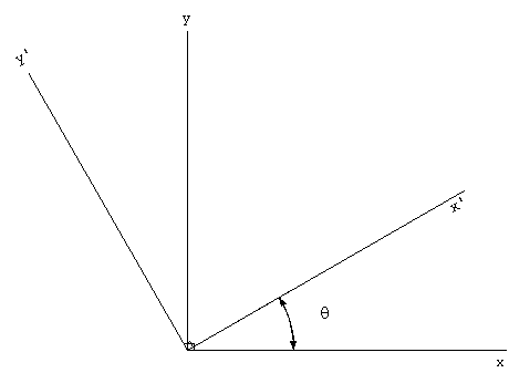
Figure 8. Rotation of
reference frame.
The measured accelerations in our body system, x'-y', are related
to the reference frame by:
ax = ax' cos q
- ay' sin q
ay = ax' sin q + ay' cos
q.
Instead of maintaining the accelerometers oriented to
an inertial reference frame, it is sufficient to know the orientation
relative to the inertial frame. This can be accomplished by a
ring laser gyro (RLG). A single RLG can measure rotation about
a single axis. A three RLG unit will measure all possible rotations.
The RLG actually measures rotation rate.
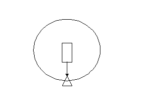
The laser in the center provides the source for two beams, one
clockwise and one counter-clockwise. Each beam will set up a
standing wave, where an integral number of wavelengths will fit
into the circumference, P. If the system is not moving, both
standing wave modes will be the same. The condition is satisfied
when
nl = P, where n = 1,2,3,…
The frequency will be f = c/l as usual.
When the system is rotating, the standing waves will change frequency
corresponding to the Doppler shift. If the ring of radius R is
rotating with angular velocity, w,
then the Doppler shift is
Df = wR/l.
The positive sign is for the counter-clockwise (+) beam. Therefore
the two modes will differ by a total of
Df = 2wR/l.
If the Doppler shift can be measured with great accuracy (it can),
then the angular rotation rate can be known at all times, which
in turn can be integrated to find the orientation angle relative
to the inertial frame. This of course must be done for each of
the three degrees of freedom for rotation. The equations are:
(1) w = lDf/2R
(2) q = w dt
Here is a picture of a complete RLG inertial navigation system:
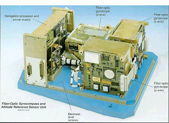
Figure 10. Typical RLG
INS.