


The Navy awarded the first production contract for AN/SLQ-32(V) to Raytheon in May 1977 and Initial Operational Capability (IOC) was achieved in FY 79. Operational Evaluation (OPEVAL) was conducted for the AN/SLQ-32(V)2 on the USS OLIVER HAZARD PERRY (FFG 7) in July 1979. In FY 82, the final Technical Evaluation (TECHEVAL) and OPEVAL were completed for the AN/SLQ-32(V)1 and (V)3 on board the USS MISSISSIPPI (CGN 40).
Shortly after production began, the Secretary of Defense directed the implementation of the Electronic Warfare Improvement Program (EWIP) to ensure that system performance was upgraded to meet evolving threats. The resulting improvements were implemented starting in 1987 and the system was given the nomenclature AN/SLQ-32A(V). Various Engineering Change Proposals (ECPs) were incorporated as part of the �Alpha� variant. Examples include Band 3 Improvements (ECP 206) which increased ES range by increasing the sensitivity in Band 3 and providing high elevation angle coverage; Digital Processor Unit (DPU) Upgrade (ECP 463) which incorporated a 20 MB hard drive, and provided a new processor that was three times faster than the old system; Interference Suppression (ECP 469) which improved Continuous Wave (CW) high pulse repetition frequency processing capability, increased the number of Band 3 Electromagnetic Interference (EMI) filters, increased the flexibility of the two existing fixed frequency notch filters, and reduced the processing load of the Digital Tracking Unit; and Semi-Omni Antenna for Band 3 (ECP 470) which provided increased isolation from own ship emitters by reducing the gain in the direction of the transmitters and sea reflections, and increased antenna gain in the direction of threats and improved elevation coverage. Additional improvements were made but were not part of the �Alpha� upgrade.
An integral component and an effective asset in the Navy�s Ship Self Defense System (SSDS), the AN/SLQ-32A Electronic Warfare System comprises three modular versions with increasing levels of complexity deployed in five variants:
RFIST Revision 1.0 was the initial research and analysis release for proof of concept. It has since been revised several times to allow autodetermination of variant and data collection on all active variants of the SLQ-32. The most recent revision (7.0) allows use of the hard disk to allow interrupted sessions to be continued from the point of interruption. RFIST Revision 7 operates in all current active versions of the AN/SLQ-32(V). This includes the AN/ SLQ-32(V)3, A(V)3, (V)4 and (V)5. The RFIST software automatically determines which variant it is installed in and operates appropriately. The operator interface is identical in all cases. Revision 7 allows use of the hard disk to temporarily store data.
Blanking has reduced or eliminated most interference from own ship�s pulsed emitters in the AN/SLQ-32(V) Countermeasures Set. Blanking disables the RF front end on a receiver that is effected by an own-ship�s pulsed emitter for a set period of time when the emitter generates an RF output pulse. To minimize degradation (receiver off-time), blanking should only occur when it is actually needed. The AN/SLA-10B Blanker Unit associated with the AN/SLQ-32 used one blanking pulse width and delay to process each pretrigger input. To ensure the interference is reduced to a minimum, the blanking pulse�s duration is set to blank the emitter�s longest pulse duration and the worst case situation of sea return. For all but worst-case situations, this adjustment will result in overblanking of the AN/SLQ-32. Optimum blanking alignment is achieved when PULSE DELAY and PULSE WIDTH controls are set to the minimum values needed to provide consistent blanking, while limiting the impact on receiver �OFF� time. Insufficient blanking will cause Own Ship emitters to be processed and dis-played, while excessive blanking reduces receiver �look time.� Blanking procedures should be performed in a normal sea state environment to minimize the effects of weather conditions on the receiving capability of the AN/SLQ-32(V). When high seas exist and sea return presents a problem, blanking pulses may be increased to compensate for reflection of ownship emitters. However, blanking pulses should be returned to normal sea state alignment settings once the weather conditions return to normal. In the past, the AN/SLQ-32 has been able to tolerate the overblanking caused by the limitations of the AN/SLA-10B with little degradation in overall system performance. However, with many of the emitters currently being introduced into the fleet, the use of large variations in pulse width and pulse repetition interval to achieve improved performance resulted in significant AN/SLA-10B overblanking (receiver off-time). One approach to resolving the problems is to develop Automated Blanking. With a blanking card that can be made smart by using a feedback loop from the AN/SLQ-32. This improved blanking card continuously readjusts the blanking pulse width based on the various activity strobe data available from the AN/SLQ-32 presorter. Due to the nature of this concept, it is only applicable to AN/SLQ-32 Bands 2 and 3. A prototype Automated Blanker has been designed and tested at NSWC Crane. The prototype consists of a temporary breakout box that extracts the feedback signals from the AN/SLQ-32 and the pretrigger signal from the AN/SLA-10B. Lab testing of the prototype is complete. An at sea test was conducted aboard the USS Klakring (FFG 42) from 28 April through 2 May 1997. If funded, this modification would be implemented as a field change (FC). Due to the extent of the FC, the conversion would be accomplished via restoration of AN/SLA-10B at NAVSURFWARCENDIV Crane. A rotatable pool would be established using decom assets. During the restoration, the required modifications would be added. The modified system would then be installed aboard ship. The upgraded DDI Console is a Standard AN/SLQ-32(V) Console with a bullnose modification allowing for control of up to six decoy launchers, FAB functionality modifications, and additional circuit cards that provide fully automated decoy launch capabilities. All AN/SLQ-32(V) units were originally slated to receive DDI Consoles; however, development of the Nulka decoy and reduced funding have limited the number of DDI Consoles being procured to approximately 40 units. When the Mk 36 Decoy Launching System is modified to add Nulka capability (changing the designation to Mk 53), all the launchers are connected to the new Decoy Launch Processor, which duplicates many of the hardware improvements found in the DDI Console. For this reason, ships with Nulka installations planned will retain the Standard Console, while the DDI Consoles under procurement will be directed toward non- Nulka ships.| Standard Console | DDI Console |
| * Operator must authorize each decoy launch | System can be configured to launch decoys without operator action |
| Control of four launchers maximum | Control of six launchers maximum |
| No direct ship's speed input | Direct ship's speed input |
| * The system selects the launchers, tubes, and reseed intervals for each engagement. The operator presses the ARM and QUICK LAUNCH FABs, when prompted, to actually launch the decoys. | |
 In February 1998, Naval Surface Warfare Center Dahlgren began
delivery of Revision 17 operational software to
AN/SLQ-32A(V)-equipped ships. Following the successful completion of Follow On Test And Evaluation (FOT&E) in April 1997 at Wallops Island, MD the Program Executive Office (PEO) Theater Air Defense (TAD) began fleet deployment of R17.00 operational software for the AN/SLQ-32A(V)3 Electronic Warfare (EW) suite. The R17.00 operational software merges capabilities certified during previous successful Operational Tests (OT) for Phase B, Rapid Anti-Ship Missile Integrated Defense System (RAIDS), and Deceptive ECM/Decoy Integration (DDI). The biggest change in R17.00 is the integration with DDI. Testing with DDI had proven to be over 95% effective in countering incoming threats. R17.00 also incorporates Software Change Proposal (SCP) changes and corrections for Feedback Reports/Trouble Reports (FBR/TR) against R16 and previous loads.
In February 1998, Naval Surface Warfare Center Dahlgren began
delivery of Revision 17 operational software to
AN/SLQ-32A(V)-equipped ships. Following the successful completion of Follow On Test And Evaluation (FOT&E) in April 1997 at Wallops Island, MD the Program Executive Office (PEO) Theater Air Defense (TAD) began fleet deployment of R17.00 operational software for the AN/SLQ-32A(V)3 Electronic Warfare (EW) suite. The R17.00 operational software merges capabilities certified during previous successful Operational Tests (OT) for Phase B, Rapid Anti-Ship Missile Integrated Defense System (RAIDS), and Deceptive ECM/Decoy Integration (DDI). The biggest change in R17.00 is the integration with DDI. Testing with DDI had proven to be over 95% effective in countering incoming threats. R17.00 also incorporates Software Change Proposal (SCP) changes and corrections for Feedback Reports/Trouble Reports (FBR/TR) against R16 and previous loads.
In order to reduce extra / false tracks R17.00 implements the correlation of new emitters with existing emitters that have a high angle change rate by use of emitter angle history to predict emitter position, it correlates different pulse repetition interval (PRI) results to the same emitter. In addition the upgrade correlated emitters to on-board radars, which allows operator to enter on-board radar parameters into a table and prevent display of emitters caused by on-board systems. The upgrade also correlate signals reported at different AOAs to the same emitter. R17.00 has the added capability to correlate Band 2 emitters in addition to the current capability for Band 3 emitters. The capabilities includes correlation of Band 2 / Band 2, Band 2 / Band 3, and Band 3 / Band 3 emitter combinations.
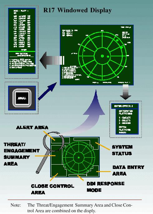
With the integration of DDI, the system can now make anticipated platform modifications. For single emitter identification, R17.00 prevents correlation of emitter candidates that don�t have anticipated platforms with existing platforms that do. It also prevents the operator from eliminating emitter candidates with anticipated platforms. Another capability is the implementation of Selected Emitter Automatic Response (SEAR) to initiate EM jamming against non-missile threats with minimum operator actions. This will compare new emitter detections against operator defined automatic engagement criteria (ELNOT, bearing sector), and engage new emitters automatically without operator intervention for positive comparisons. Display modifications were added to improve human machine interface. The improvements were made possible by replacing most tabular displays with windowed displays that can be inspected and changed without leaving the polar display. The displays allow the operator to sequence to and review alerts without losing information entered during a prompting sequence. R17.00 implements scan algorithm improvements that increase the number of emitters for which scan can be successfully determined and allow scan to be determined even under conditions of dropped lobes or staggered/pulse group emitter types. A modification has been added in order to automatically suspend engagement of and release resources assigned to a non-missile emitter whenever the emitter becomes inactive (i.e. Digital Tracking Unit (DTU) sends delete emitter message to Digital Processor Unit (DPU)). Then the software will resume engagement automatically whenever the emitter becomes re-activated. R17.00 has been modified for anticipated platforms; to display only platforms that could be active in the current Geo-area. Other software modifications include: the check for duplicate platform name text strings whenever an addition is made to the Platform Name File and will alert the operator of duplication, allowing the operator to perform Multi-Emitter Correlation (MEC) operations in Polar mode , order non-primary ID candidates in close control display in descending order of threat level, and the Expand Threat Data Base (formerly Main Line Threat Library). The Expand Threat Data Base has the following modifications:
The decommissioning of ships with installed AN/SLQ-32(V)s provide assets to be used on new ships. Rather than award additional contracts for new production systems, the US Navy decided to restore systems from decommissioned platforms. The Navy terminated production of new systems after Lot 15 and implemented a joint effort between NSWCCD and Raytheon for the restoration of systems. A total of 450 systems, US and FMS, were procured through Lot 15. In November 1995, the Navy awarded Raytheon a contract for restoration of three AN/SLQ-32A(V)3s. NSWCCD restored and upgraded parts of the system and prepared enclosures for installation of articulated doors. The hardware was then shipped to Raytheon for assembly and sell-off. The Navy awarded another restoration contract for eight AN/SLQ-32A( V)2s and one A(V)3 in the second quarter of FY 98.
CNO Memo of 14 May 1996 Ser 00/6C5000044 terminated the AN/SLQ-32(V) Program and directed reprogramming of funding to the Advanced Integrated EW System (AIEWS) Program. Because of its advancing age and the incremental introduction of AIEWS, the AN/SLQ-32(V) Fleet assets will require support well into the twenty-first century. As the replacement for AN/SLQ-32(V), AIEWS will use an open systems architecture to lower investment costs and improve system effectiveness. Due to the open design, this system will allow for ease of future technology insertion, dramatically improve human computer interface to promote smartship manning, and promote full integration with the shipboard LAN and combat systems. The Navy will introduce AIEWS in two increments: the first designed to provide improved human-computer interface, improved emitter processing, a new receiver package including a special signal receiver, specific emitter identification capability, and enhanced combat system integration; and, the second increment is to include an advanced electronic attack subsystem.
All AN/SLQ-32(V) procurements through DDG 79 were completed under Lot 16. DDGs 80-83 will utilize new AN/SLQ-32A(V)3s from Lot 15 or restored systems from Lot 16. DDGs 84-90 and LPD 17 are currently scheduled to receive restored AN/SLQ-32A( V)2 systems. When funds become available, LPD 18-21 will receive re-stored AN/SLQ-32A(V)2s if it is still a viable option. DDGs 91 and beyond as well as LPD 22 and beyond are currently planned to receive forward fit AIEWS.
Included with the AN/SLQ-32A is the Electronic Warfare On-Board Trainer (EW OBT) S10H7, a Personal Computer (PC) based training system, which synthesizes and injects simulated, programmable emitter contact signals into AN/SLQ-32A EW equipment in support of dockside or at-sea training exercises. Digital and video/audio training signals representing the ship's electromagnetic environment are injected into EW system components, and are conditioned to simulate the signal characteristics of a large cross section of platform emitters. The EW OBT is capable of running either preprogrammed or dynamically built scenarios via PC interface; and it is capable of simulating over 150 emitters simultaneously. EW OBT scenarios can be either locally controlled to provide operator level training, or externally driven to support integrated Combat System team level training. The EW OBT utilizes the embedded training device to interface with EW components and provide emitter simulation, which is compatible with the on-line threat library, operator control requests, signal analysis capability, and close control. Simulated emitter characteristics specified by the scenario are selected and controlled by the embedded training device relational database management system software.
AN/SLQ-32(V) SOFTWARE CONFIGURATION STATUS ACCOUNTING REPORT
U.S. SHIPS BY CLASS - ** INFO ONLY **
Data as of Tuesday, November 17, 1998
ANCHORAGE CLASS
Ship Hull Configuration Coast Variant
ANCHORAGE LSD 36 --/O3 WEST V1
MOUNT VERNON LSD 39 --/O3 WEST V1
PENSACOLA LSD 38 --/O3 EAST V1
PORTLAND LSD 37 --/O3 EAST V1
ARLEIGH BURKE CLASS
Ship Hull Configuration Coast Variant
ARLEIGH BURKE DDG 51 AN1 EAST V2
BENFOLD DDG 65 AN1 WEST V2
CARNEY DDG 64 AN1 EAST V2
COLE DDG 67 AN1 EAST V2
CURTIS WILBUR DDG 54 AN1 WEST V2
DECATUR DDG 73 AN1 EAST V3
DONALD COOK DDG 75 AN1 EAST V3
FITZGERALD DDG 62 AN1 WEST V2
GONZALEZ DDG 66 AN1 EAST V2
HIGGINS DDG 76 AN1 WEST V3
HOPPER DDG 70 AN1 WEST V3
JOHN BARRY DDG 52 AN1 EAST V2
JOHN PAUL JONES DDG 53 AN1 WEST V2
JOHN S. MCCAIN DDG 56 AN1 WEST V2
LABOON DDG 58 AN1 EAST V2
MAHAN DDG 72 AN1 EAST V3
MCFAUL DDG 74 AN1 EAST V3
MILIUS DDG 69 AN1 WEST V3
MITSCHER DDG 57 AN1 EAST V2
PAUL HAMILTON DDG 60 AN1 WEST V2
PORTER DDG 78 AN1 EAST V3
RAMAGE DDG 61 AN1 EAST V2
ROSS DDG 71 AN1 EAST V3
RUSSELL DDG 59 AN1 WEST V2
STETHEM DDG 63 AN1 WEST V2
STOUT DDG 55 AN1 EAST V2
THE SULLIVANS DDG 68 AN1 EAST V3
AUSTIN CLASS
Ship Hull Configuration Coast Variant
AUSTIN LPD 4 --/O3 EAST V1
CLEVELAND LPD 7 --/O3 WEST V1
DENVER LPD 9 --/O3 WEST V1
DUBUQUE LPD 8 --/O3 WEST V1
DULUTH LPD 6 --/O3 WEST V1
JUNEAU LPD 10 --/O3 WEST V1
NASHVILLE LPD 13 --/O3 EAST V1
OGDEN LPD 5 --/O3 WEST V1
PONCE LPD 15 --/O3 EAST V1
SHREVEPORT LPD 12 --/O3 EAST V1
TRENTON LPD 14 --/O3 EAST V1
AUXILIARY COMMAND SHIPS CLASS
Ship Hull Configuration Coast Variant
CORONADO AGF 11 --/O3 WEST V1
LASALLE AGF 3 --/O3 EAST V1
BLUE RIDGE CLASS
Ship Hull Configuration Coast Variant
BLUE RIDGE LCC 19 AO1 WEST V3
MOUNT WHITNEY LCC 20 AO1 EAST V3
CALIFORNIA CLASS
Ship Hull Configuration Coast Variant
CALIFORNIA CGN 36 AO1 WEST V3
SOUTH CAROLINA CGN 37 O1/O3 EAST V3
ENTERPRISE CLASS
Ship Hull Configuration Coast Variant
ENTERPRISE CVN 65 N/A EAST V4
FAMOUS CUTTER(USCGC) CLASS
Ship Hull Configuration Coast Variant
BEAR WMEC 901 AO1 N/A V2
CAMPBELL WMEC 909 AO1 N/A V2
ESCANABA WMEC 907 AO1 N/A V2
FORWARD WMEC 911 AO1 N/A V2
HARRIET LANE WMEC 903 AO1 N/A V2
LEGARE WMEC 912 AO1 N/A V2
MOHAWK WMEC 913 AO1 N/A V2
NORTHLAND WMEC 904 AO1 N/A V2
SENECA WMEC 906 AO1 N/A V2
SPENCER WMEC 905 AO1 N/A V2
TAHOMA WMEC 908 AO1 N/A V2
TAMPA WMEC 902 AO1 N/A V2
THETIS WMEC 910 AO1 N/A V2
HARPERS FERRY CLASS
Ship Hull Configuration Coast Variant
CARTER HALL LSD 50 A-- EAST V1
HARPERS FERRY LSD 49 A-- WEST V1
OAK HILL LSD 51 A-- EAST V1
PEARL HARBOR LSD 52 A-- EAST V1
INCHON CLASS
Ship Hull Configuration Coast Variant
INCHON MCS 12 AO1 EAST V3
IWO JIMA CLASS
Ship Hull Configuration Coast Variant
GUAM LPH 9 O1/O3 EAST V3
KIDD CLASS
Ship Hull Configuration Coast Variant
CHANDLER DDG 996 AO1 WEST V2
SCOTT DDG 995 AO1 EAST V3
KILAUEA CLASS
Ship Hull Configuration Coast Variant
MOUNT HOOD AE 29 --/O3 WEST V1
SANTA BARBARA AE 28 --/O3 EAST V1
KITTY HAWK CLASS
Ship Hull Configuration Coast Variant
CONSTELLATION CV 64 N/A WEST V4
KITTY HAWK CV 63 N/A WEST V4
NIMITZ CLASS
Ship Hull Configuration Coast Variant
ABRAHAM LINCOLN CVN 72 N/A WEST V4
CARL VINSON CVN 70 N/A WEST V4
DWIGHT D. EISENHOWER CVN 69 N/A EAST V4
GEORGE WASHINGTON CVN 73 N/A EAST V4
HARRY S. TRUMAN CVN 75 N/A EAST V4
JOHN C. STENNIS CVN 74 N/A WEST V4
NIMITZ CVN 68 N/A WEST V4
THEODORE ROOSEVELT CVN 71 N/A EAST V4
OLIVER HAZARD PERRY CLASS
Ship Hull Configuration Coast Variant
BOONE FFG 28 AO1 EAST V2
CARR FFG 52 AO1 EAST V5
CLARK FFG 11 AO1 EAST V2
CROMMELIN FFG 37 AO1 WEST V2
CURTS FFG 38 AO1 WEST V2
DE WERT FFG 45 AO1 EAST V5
DOYLE FFG 39 AO1 EAST V2
ELROD FFG 55 AO1 EAST V5
ESTOCIN FFG 15 O1/O3 EAST V2
FORD FFG 54 AO1 WEST V5
GARY FFG 51 AO1 WEST V5
GEORGE PHILIP FFG 12 AO1 WEST V2
HALYBURTON FFG 40 AO1 EAST V5
HAWES FFG 53 AO1 EAST V5
INGRAHAM FFG 61 AO1 WEST V5
JARRETT FFG 33 AO1 WEST V2
JOHN A. MOORE FFG 19 AO1 WEST V2
JOHN L. HALL FFG 32 AO1 EAST V5
KAUFFMAN FFG 59 AO1 EAST V5
KLAKRING FFG 42 AO1 EAST V2
LEWIS B. PULLER FFG 23 AO1 WEST V2
MCCLUSKY FFG 41 AO1 WEST V2
MCINERNEY FFG 8 AO1 EAST V2
NICHOLAS FFG 47 AO1 EAST V5
REID FFG 30 O1/O3 WEST V2
RENTZ FFG 46 AO1 WEST V5
REUBEN JAMES FFG 57 AO1 WEST V5
ROBERT G. BRADLEY FFG 49 AO1 EAST V5
RODNEY M. DAVIS FFG 60 AO1 WEST V2
SAMUEL B. ROBERTS FFG 58 AO1 EAST V5
SAMUEL E. MORISON FFG 13 O1/O3 EAST V2
SIDES FFG 14 O1/O3 WEST V2
SIMPSON FFG 56 AO1 EAST V5
STARK FFG 31 AO1 EAST V2
STEPHEN W. GROVES FFG 29 AO1 EAST V5
TAYLOR FFG 50 AO1 EAST V5
THACH FFG 43 AO1 WEST V2
UNDERWOOD FFG 36 AO1 EAST V5
VANDEGRIFT FFG 48 AO1 WEST V5
WADSWORTH FFG 9 AO1 WEST V2
SACRAMENTO CLASS
Ship Hull Configuration Coast Variant
CAMDEN AOE 2 AN1 WEST V3
DETROIT AOE 4 AO1 EAST V3
SACRAMENTO AOE 1 AO1 WEST V3
SEATTLE AOE 3 AO1 EAST V3
SPRUANCE CLASS
Ship Hull Configuration Coast Variant
ARTHUR W. RADFORD DD 968 AO1 EAST V2
BRISCOE DD 977 AN1 EAST V3
CARON DD 970 AO1 EAST V2
CONOLLY DD 979 AN1 EAST V3
CUSHING DD 985 AN1 WEST V3
DAVID R. RAY DD 971 AO1 WEST V2
DEYO DD 989 AN1 EAST V3
ELLIOT DD 967 AO1 WEST V2
FIFE DD 991 O1/O3 WEST V2
FLETCHER DD 992 AN1 WEST V3
HAYLER DD 997 AN1 EAST V3
HEWITT DD 966 AO1 WEST V2
INGERSOLL DD 990 O1/N3 WEST V2
JOHN HANCOCK DD 981 AO1 EAST V2
JOHN RODGERS DD 983 AN1 EAST V3
JOHN YOUNG DD 973 AN1 WEST V3
KINKAID DD 965 AO1 WEST V3
MOOSBRUGGER DD 980 AN1 EAST V3
NICHOLSON DD 982 AN1 EAST V3
O BANNON DD 987 AN1 EAST V3
O BRIEN DD 975 O1/O3 WEST V2
OLDENDORF DD 972 AN1 WEST V3
PAUL F. FOSTER DD 964 AN1 WEST V3
PETERSON DD 969 AN1 EAST V3
SPRUANCE DD 963 AN1 EAST V3
STUMP DD 978 AN1 EAST V3
THORN DD 988 AN1 EAST V3
SUPPLY CLASS
Ship Hull Configuration Coast Variant
ARCTIC AOE 8 AN1 EAST V3
BRIDGE AOE 10 AN1 WEST V3
RAINIER AOE 7 AN1 WEST V3
SUPPLY AOE 6 AN1 EAST V3
TARAWA CLASS
Ship Hull Configuration Coast Variant
BELLEAU WOOD LHA 3 AO1 WEST V3
NASSAU LHA 4 AO1 EAST V3
PELELIU LHA 5 AO1 WEST V3
SAIPAN LHA 2 AO1 EAST V3
TARAWA LHA 1 AO1 WEST V3
TICONDEROGA CLASS
Ship Hull Configuration Coast Variant
ANTIETAM CG 54 AO1 WEST V3
ANZIO CG 68 AN1 EAST V3
BUNKER HILL CG 52 AO1 WEST V3
CAPE ST GEORGE CG 71 AN1 EAST V3
CHANCELLORSVILLE CG 62 AN1 WEST V3
CHOSIN CG 65 AN1 WEST V3
COWPENS CG 63 AN1 WEST V3
GETTYSBURG CG 64 AN1 EAST V3
HUE CITY CG 66 AN1 EAST V3
LAKE CHAMPLAIN CG 57 AO1 WEST V3
LAKE ERIE CG 70 AN1 WEST V3
LEYTE GULF CG 55 AO1 EAST V3
MOBILE BAY CG 53 AO1 WEST V3
MONTEREY CG 61 AN1 EAST V3
NORMANDY CG 60 AN1 EAST V3
PHILIPPINE SEA CG 58 AO1 EAST V3
PORT ROYAL CG 73 AN1 WEST V3
PRINCETON CG 59 AN1 WEST V3
SAN JACINTO CG 56 AO1 EAST V3
SHILOH CG 67 AN1 WEST V3
THOMAS S. GATES CG 51 AO1 EAST V3
TICONDEROGA CG 47 AO1 EAST V3
VALLEY FORGE CG 50 AO1 WEST V3
VELLA GULF CG 72 AN1 EAST V3
VICKSBURG CG 69 AN1 EAST V3
VINCENNES CG 49 AO1 WEST V3
YORKTOWN CG 48 AO1 EAST V3
WASP CLASS
Ship Hull Configuration Coast Variant
BATAAN LHD 5 AN1 EAST V3
BONHOMME RICHARD LHD 6 AN1 EAST V3
BOXER LHD 4 AN1 WEST V3
ESSEX LHD 2 AN1 WEST V3
KEARSARGE LHD 3 AN1 EAST V3
WASP LHD 1 AN1 EAST V3
WHIDBEY ISLAND CLASS
Ship Hull Configuration Coast Variant
ASHLAND LSD 48 A-- EAST V1
COMSTOCK LSD 45 A-- WEST V1
FORT MCHENRY LSD 43 A-- WEST V1
GERMANTOWN LSD 42 --/O3 WEST V1
GUNSTON HALL LSD 44 A-- EAST V1
RUSHMORE LSD 47 A-- WEST V1
TORTUGA LSD 46 A-- EAST V1
WHIDBEY ISLAND LSD 41 A-- EAST V1