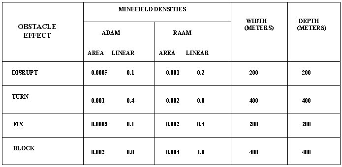
The family of scatterable mines adds new dimension to mine warfare, providing the maneuver commander with a rapid, flexible means of delaying, harassing, paralyzing, canalizing, or wearing down the enemy forces in both offensive and defensive operations. Mines can force the enemy into kill zones, change their direction of attack, spend time in clearing operations, or take evasive actions. FASCAM presents an array of air and FA-delivered scatterable mines available to maneuver force commanders. The systems- GATOR (USAF Delivered), VOLCANO (ground or air delivered), ADAM/RAAM (artillery delivered) and MOPMS (Modular Pack Mine System) have special considerations such as planning time, availability, survivability of system and logistical requirements.
Scatterable mine systems enable the tactical commanders to emplace minefields in enemy held terrain, contaminated territory, or in others areas where it is not possible to emplace conventional minefields. They are designed to be delivered or dispensed remotely by aircraft, artillery, or by ground dispenser. Minefields are laid without a clear pattern. All FASCAM mines have a active life cycle and self-destruct (SD) time after their active life has expired. The duration of the active life varies from 4 hours to 15 days depending on the system. FASCAM minefields are planned by the commander's staff engineer in concert with the commander's intent and systems availible. The staff engineer determines location, size, time and density of the minefields. He coordinates with appropriate staff officers to ensure systems are available at the time and location for placement.CAPABILITIES.
Faster response. Units can place scatterable mines faster than conventional mines, so they provide the commander with greater flexibility, and allow reaction to changing in situations. The use of scatterable mines can allow the commander to maintain or regain the initiative by allowing units to act faster than the enemy. This also helps preserve scarce mine resources.
Remote emplacement. Scatterable mines are remotely placed. This enhances battlefield agility and allows the maneuver commander to rapidly place mines to best exploit enemy weaknesses. Commander�s can use scatterable mines as a situational obstacle; as a reserve obstacle emplacement capability; and to directly attack enemy formations through disrupt, fix, turn, and block. Modern fusing, sensing, and antidisturbance devices allow scatterable mines to better defeat enemy attempts to reduce the minefield.
Increased tactical flexibility. After allowing enough time for the minefield to self-destruct, the minefield is cleared, and the commander can move through an area that was previously denied to enemy or friendly forces. In many cases, the self-destruct period may be set at only a few hours. This feature allows for effective counterattacks to the enemy�s flanks and rear areas.
Efficiency. There are a variety of ways to deliver and place scatterable mines. Methods include delivery by fixed-wing aircraft, helicopters, artillery, or ground vehicles. They satisfy the high-mobility requirements of modern warfare. Scatterable mines are much smaller and lighter than conventional mines and require less manpower, equipment and tonnage to place.
Increased lethality. Scatterable AT mines use a self-forging fragmentation (SFF) created from a two-sided Miznay-Shardin (M-S) plate charge to produce a full-width kill. In simple terms, a metal plate is formed into a super-dense molten rock that punches a hole in the belly of the tank. This produces an M-Kill against the vehicle engine, track, or drive train; a firepower kill against the vehicle weapon system; or a K-Kill in which the on-board sets off ammunition, which kills or incapacitates the crew. The scatterable AT mine can kill any tank in the world. In order to form the SFF; the mine requires a standoff between the vehicle and the target. Mines must also be nearly perpendicular to the target (lying on either side). The two- sided design of the M-S plate allows the mine to successfully attack the target while lying on either side. Trip wires actuate scatterable AP mines and utilize a blast/fragmentation-type kill mechanism.
LIMITATIONS.
Extensive coordination. Scatterable mines are very dynamic weapon systems and require great care to ensure proper coordination with higher, adjacent, and subordinate units. Brigades must notify all affected units of the location and duration of scatterable minefields in order to prevent friendly casualties. Recording and reporting procedures for scatterable mines exist to help minimize this problem.
Proliferation of targets. Some commanders may regard scatterable mines as an easy solution to tactical problems. Commander must carefully evaluated, and prioritize tactical requests. Indiscriminate use of scatterable mines results in rapid depletion of a unit�s basic load. Controlled supply rates (CSRs) will probably be a constraint in all theaters.
Visibility. Scatterable mines are very effective, even though they lie exposed on the surface of the ground because they are relatively small and have natural colorings. Using scatterable mines in conjunction with fires and obscurants increases their effectiveness and strains the enemy�s command and control.
Accuracy. Units cannot lay scatterable mines with the same accuracy as conventional mines; however, their self-destruct capability eliminates the need for recovering them. Remotely delivered scatterable mine systems are as accurate as conventional artillery or tactical aircraft-delivered munitions.
Orientation. 5 to 15 percent of scatterable mines will come to rest on their edge. If there is mud or snow more than 10 centimeters deep, mines will be in the higher percentile. Classified lethality data provides for 10 percent of scatterable mines to rest on their edge. When employing the area denial artillery munition (ADAM) and the remote antiarmor mine (RAAM) in over 10 centimeters of snow, units should use high-angle fire and increase the number of mines. Using AP mines in snow may be less effective because it hinders the deployment of trip wires. Melting snow may also cause mines to change position and activate antidisturbance features.
Antipersonnel Mines
There are two general categories of AP SCATMINEs--wedge-shaped and cylindrical .
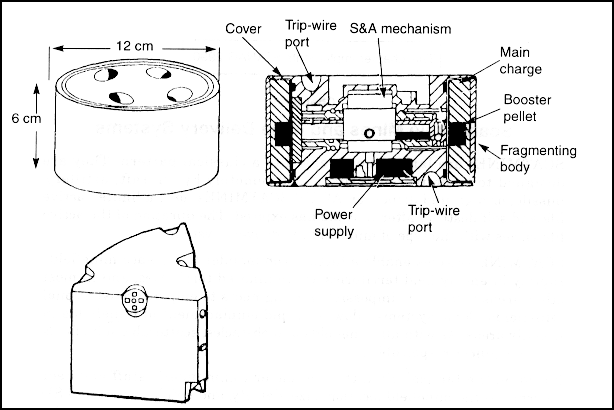
AP SCATMINEs
The M67 and M72 AP SCATMINEs are wedge-shaped and dispensed from an ADAM projectile, which is a special 155-millimeter artillery munition. Each mine weighs 540 grams and is 7 centimeters high.
The M74, BLU 92/B, M77, and Volcano AP SCATMINEs are all cylindrical in shape. They are 6 centimeters high and 12 centimeters in diameter. Cylindrical AP SCATMINEs kill enemy soldiers through the combined effects of blast and fragmentation. Each mine contains 540 grams of composition B4 as its main charge. The charge detonates upon actuation and shatters the mine's metal casing to produce shrapnel. Shrapnel is propelled upward and outward from the mine and produces fatal casualties to a distance of 15 meters. Each mine has eight trip wires (four on the top and four on the bottom) that deploy after ground impact up to 12 meters from the mine. Trip wires are similar in appearance to very fine thread; they are olive-drab green in color and weighted at the free end. A tension of 405 grams applied to one trip wire is enough to create a break in the electrical circuit and cause the mine to detonate.
ANTITANK MINES
All AT SCATMINEs have similar functional characteristics. They are cylindrical in shape, weigh approximately 1.8 kilograms, contain 585 grams of cyclonite (RDX) explosive as the main charge, and have a magnetically induced fuse. The characteristics of each AT SCATMINE are summarized in Table 3-2.
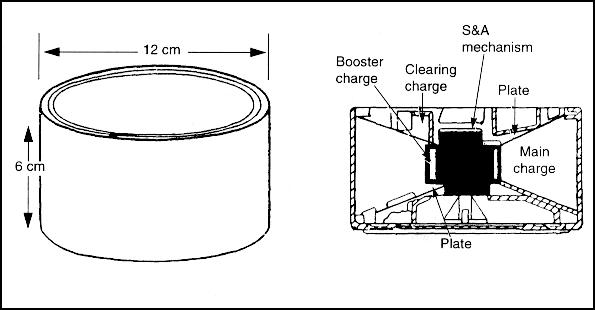
AT SCATMINE
AT SCATMINEs are designed to produce a K-Kill (kill the crew of the vehicle) instead of an M-Kill. They produce a kill by using an SFF warhead (created from a two-sided M-S plate). The warhead penetrates the vehicle's belly armor, and spalling metal from the vehicle (created by the mine blast or secondary explosions) kills occupants instantly. Even though the crew is killed, the drive train may be undamaged and the vehicle may continue to move. On enemy tanks with autoloaders, the detonation of rounds in the belly-mounted ammunition carousel is very likely. The mine may not achieve a kill when the track of an armored vehicle runs directly over it.
All mines have a safe-arm time from (45 seconds to 2 minutes). When mines fail to arm they will self-destruct immediately. SD times are not exact, mines actually self-destruct in a window between 80 to 100 percent of their SD time ie. mines with a 4 hour SD time will start to SD in 3 hours 12 minutes. If a mine fails to SD it should be treated as UXO.
Short duration <24 hour SD time
Long duration >24 hour SD time
Reference FM 20-32, page 7-1
FASCAM QUICK REFERENCE
| TYPE | ARM | SHORT | LONG |
| ADAM/RAAM | 2 MIN/45 SEC | 4 HR | 48 HR |
| VOLCANO | 2 MIN | 4 HR | 48 HR/15D |
| MOPMS | 2 MIN | 4 HR | REC 15 D |
| GATOR | 2 MIN | 4 HR | 48 HR/15 D |
| TYPE | DENSITY | SIZE | SFTY ZN |
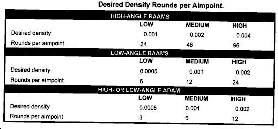
| ADAM/RAAM | .001, .002, .004 | 200 X 200 | 1400 X 1400 |
| .001, .002, .004 | 400 X 400 | 1500 X 1500 | |
| VOLCANO (GND) | 0.01 | 1195 X 170 | 235 ALL SIDES |
| (AIR) | 0.0067 | 1000 X 150 | 235 ALL SIDES |
| MOPMS | 0.01 | 35 - 180 DEG | 235 ALL SIDES |
| GATOR | 0.003 | 650 X 200 | 275 ALL SIDES |
Two types of minefields can be developed with FASCAM--planned minefield and target of opportunity minefields.
Planned minefields begin with the development of the scheme of maneuver and then the barrier and/or obstacle plan by the G3 and/or S3 and engineer. Before deciding on the employment of ADAM and/or RAAMS, the FSCOORD is brought into the planning process to provide guidance on the availability of FA mines and delivery units.
Minefields employed against targets of opportunity (unplanned) must be emplaced immediately because of the tactical nature of the targets. They are requested through the fire support channels at any level. Once the maneuver brigade or division commander has approved the use of FA mines, they can be emplaced appropriately. Normally, targets of opportunity are used when the delivery of the mines can be observed. Aimpoints for target of opportunity minefields can be computed as in a planned minefield. However, this will be time-consuming and may not meet the demands of the tactical situation. Therefore, it is recommended that units establish an SOP for a "standard minefield" to fire when the tactical situation requires an immediate minefield. For example, the unit SOP may be for a 400 x 400 minefield, high angle, medium density, with two aimpoints. The SOP will allow FSOs to determine the number of target of opportunity minefields that are available for the maneuver commander. This determination is based on the unit's FASCAM unit basic load (UBL).
FASCAM employment is based on a concept known as planning modules. The planning module for RAAMS low angle is 200 meters x 200 meters. The planning module for RAAMS high angle and for ADAM low or high angle is 400 meters x 400 meters. This does not mean that the minefield planner cannot request a minefield that is larger than the planning module. In any FASCAM minefield, the requesting agency defines the minefield size in terms of the length, width, and attitude. The length of the minefield is always the longest axis. The concept of the planning modules is based on the minefield width. In other words, the width of all minefields must be in multiples of the planning module defined above. The FDO will use the length, width, and planning module to determine the number of linear sheafs required to establish the required minefield. The linear sheafs will evenly divide each module and will be parallel to the long axis (length) of the minefield.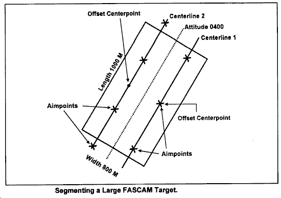

EMPLOYMENT
MULTIPLE OFFENSIVE/DEFENSIVE ROLES
DOES NOT REQUIRE COMMITTING GROUND/AIR UNITS FOR EMPLOYMENT
DESIGNED FOR FLEXIBLE RESPONSE
TIME AND ROUNDS REQUIRED TO EMPLOY LIMIT USE
LIMITED BY RANGE TO AIRLAND BATTLE DOCTRINE
NECESSARY TO PLOT SAFETY ZONE
DURATION AND NET/NLT EMPLACEMENT
EMPLACEMENT
REQUESTED THROUGH NORMAL ARTILLERY SUPPORT CHANNELS
CLOSE COORDINATION BETWEEN G3/S3, ENGINEER, AND FSCOORD REQUIRED
ENGINEER RESPONSIBILITIES:
*RECOMMENDS LOCATION, SIZE, TYPE, TGT, EFFECT, AND DURATION
*CONDUCTS COORDINATION WITH G3/S3 AND FSE FOR NET/NLT EMPLACEMENT AND DENSITY
*PLOTS SAFETY ZONE ON MANEUVER COMMANDER�S MAP
FSCOORD RESPONSIBILITIES:
*NUMBER OF ROUNDS FOR REQUIRED DENSITY
*TIME REQUIRED TO EMPLACED
*NUMBER AND LOCATION OF AIM POINTS
*ADVISES ENGINEER OF FEASIBILITY OF PLAN AND TECHNICAL ASPECTS
*ISSUE SCATMINWARN AND SCATMINREP
Reference FM 20-32, pages 6-8 to 6-11
ADAM/RAAM


