Specifications
|
| Performance Factors |
EC-135 |
EC-18B |
| Max Takeoff Gross Wt (lb) |
300,500 |
326,000 |
| Normal Cruise Speed (kt TAS) |
430 |
450 |
| Max Cruise Speed (kt TAS) |
490 |
470 |
Nominal Support Speed -
30kft (kt TAS) |
360/420 |
360/420 |
Nominal Turning Radius -
30 kft, 30 deg bank (nm) |
3.3/4.5 |
3.3/4.5 |
Minimum Turning Radius -
30 kft, 45 deg bank (nm) |
1.9/2.6 |
1.9/2.6 |
Nominal Turn Time, 180 deg -
30 kft, 30 deg bank (min) |
1.7/1.8 |
1.7/1.8 |
Minimum Turn Time, 180 deg -
30 kft, 45 deg bank (min) |
1.0/1.2 |
1.0/1.2 |
| Nominal Operating Altitude (ft MSL) |
30,000 |
30,000 |
| Maximum Operating Altitude (ft MSL) |
33,000 |
42,000 |
| Mission Operating Altitude (ft MSL) |
5,000 to 33,000 |
500 to 42,000 |
| Range |
The range capability of the ARIA is influenced by:
- Aerial refueling capability
- Runway length, obstacle clearance, and noise abatement restrictions
- Runway elevation
- Runway air temperature
- Distance to alternate base
- Fuel reserve requirements
- Enroute wind conditions
- Aircraft altitude during data run
Application of the above factors to some 25 worldwide airports produces maximum ranges varying from 2,800 to 4,500 nm without aerial refueling. Two ARIA currently have the capability to take on fuel while in flight. This greatly extends the maximum attainable range.
|
| Navigation |
- Dual TACAN
- Dual VOR
- ADF radio
- Omega
- N-1 compass system*
- True airspeed indication system
- APN-59 search radar on EC-135E; RDR-1F on EC-18B
- APN-218 Doppler radar*
- Periscopic sextant
- Dual Inertial Navigation System (INS)
- Global Positioning System (GPS)
*EC-135E only
|
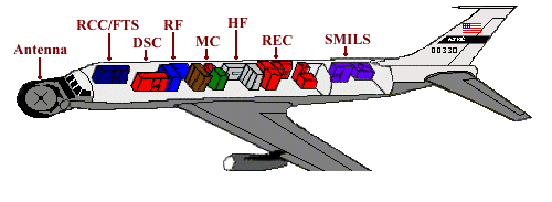 ARIA Prime Mission Electronic Equipment (PMEE)


 The 452nd Flight Test Squadron at Edwards Air Force Base operates a variety of
unique, highly modified C-135 and C-18 aircraft to plan and execute DoD, NASA, and
operational flight test programs. Missions supported include worldwide telemetry
gathering, international treaty verification, spacecraft launches, ballistic missile defense, electronic combat and vulnerability analysis, aircraft icing tests, and aerial refueling certification. The 452 FLTS accomplishes its primary mission using the Advanced Range Instrumentation Aircraft (ARIA) and the Cruise Missile Mission Control Aircraft (CMMCA).
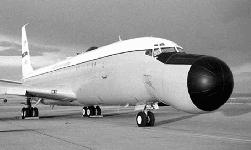
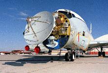
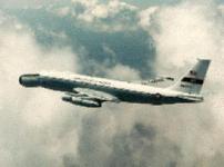
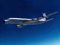
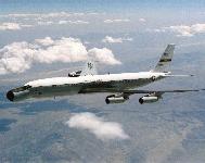
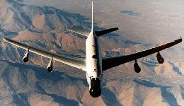
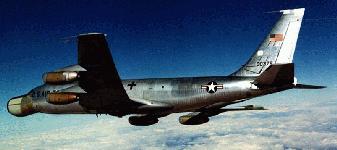
The Advanced Range Instrumentation Aircraft (ARIA - pronounced Ah-RYE-ah) are EC-135E and EC-18B aircraft used as flexible airborne telemetry data recording and relay stations. These aircraft were designed and developed to supplement land and marine telemetry stations in support of DOD and NASA space and missile programs. The ARIA have the capability to acquire, track, record, and
retransmit telemetry signals, primarily in the S-band (2200-2400 MHz)
frequency range.
In the early 1960's, the National Aeronautics and Space Administration
(NASA) realized that the lunar missions of the Apollo program would require a
worldwide network of tracking and telemetry stations, many positioned in
remote regions of the world. The Department of Defense (DoD) was also
faced with similar considerations for its unmanned orbital and ballistic missile
reentry test programs. Since land stations are obviously limited by geographical
constraints, and instrumentation ships cannot be moved quickly enough to
cover different positions during the same mission, it soon became evident that
large gaps in coverage would occur. To fill these gaps, a new concept in
tracking stations was developed - a high-speed aircraft containing the
necessary instrumentation to assure spacecraft acquisition, tracking, and
telemetry data recording. The same aircraft could provide coverage of
translunar injection and recovery for NASA's manned space flight operations,
as well as events of interest in the DoD orbital or ballistic missile reentry tests.
To implement the concept, NASA and DoD jointly
funded the modification of eight C-135 jet transport/cargo aircraft. The Apollo/Range
Instrumentation Aircraft (A/RIA),
designated EC-135N, became operational in January 1968, having been
modified at the basic cost of $4.5 million per aircraft.
The Air Force Eastern Test Range (AFETR) was
selected to operate and maintain the system in support of the test and
evaluation (T&E) community. McDonnell-Douglas Corporation and Bendix
Corporation were the contractors for the design, aircraft modification, and
testing of the electronic equipment.
In December 1975, after 7 years of operation by the Eastern Test
Range, the ARIA (redesignated Advanced Range Instrumentation Aircraft
following completion of the Apollo program) were transferred to the 4950th
Test Wing, Wright-Patterson AFB, Ohio, as part of an Air Force consolidation
of large T&E aircraft. The 4950th Test Wing provided test support, personnel,
and resources for the operational use of, and modifications and improvement
to, the ARIA fleet. After arriving at Wright-Patterson AFB, the ARIA fleet underwent
numerous conversions, including re-engining of EC-135N ARIA to EC-135E
and the acquisition and conversion of used Boeing 707 commercial airliners to
ARIA.
In 1982, the Air Force bought eight used Boeing 707-320C's from American Airlines, modifying the jets to the ARIA configuration and dubbing them EC-18B's. The EC-18B, which is larger than the EC-135N, carries a bigger payload and operates on shorter runways, flew its first mission in January 1986 out of Kenya. In 1994, the ARIA fleet was relocated to Edwards AFB, California, as part of the 452d Flight Test Squadron, in the 412th Test Wing. The current ARIA fleet consists of three EC-135E and three EC-18B aircraft. On 10 February 1998 the annual Force Structure Announcement formalized adjustments to the aircraft fleet at Edwards, which included the loss of one EC-18 and one EC-135 aircraft. These changes were the result a continuation of the normal fleet adjustments which occur at Edwards as test programs change and the general test aircraft fleet is upgraded and modernized.

