ASSIGNMENT SHEET
DEGAUSSING
Assignment Sheet Number 62B-303
INTRODUCTION
A steel-hulled ship is like a huge floating magnet with a large magnetic field surrounding it. As the ship moves through the water, this field also moves and adds to or subtracts from the Earth's magnetic field. Because of its distortion effects on the Earth’s magnetic field, the ship can act as a trigger device for magnetic sensitive ordnance or devices which are designed to detect these distortions. The degaussing system is installed aboard ship to reduce the ship's effect on the Earth's magnetic field. In order to accomplish this, the change in the Earth's field about the ship's hull is "canceled" by controlling the electric current flowing through degaussing coils wound in specific locations within the hull. This, in turn, reduces the possibility of detection by these magnetic sensitive ordnance or devices.
LESSON TOPIC LEARNING OBJECTIVES
Terminal Objective:
16.0 DESCRIBE the location, function and operation of the ships interior communication systems.
Enabling Objective(s):
16.47 DEFINE the following:
A. Earth's magnetic field
B. Ship's permanent magnetization
C. Ship's induced magnetization
D. Ship's magnetic field
E. Deperming
F. Degaussing
16.48 EXPLAIN the following components of the Earth's magnetic field:
A. Horizontal
B. Vertical
C. Longitudinal
D. Athwartship
16.49 DESCRIBE the function of the degaussing system.
16.50 DESCRIBE the following items:
A. Automatic degaussing operations
B. Manual degaussing operations
C. Degaussing switchboard
D. Remote operation panels
E. Degaussing coils
16.51 DESCRIBE why the electric current in the various degaussing coils must be varied due to the ship's heading and geographic location.
16.52 DISCUSS the function of the compass compensating coil.
16.53 DESCRIBE the Degaussing Folder.
16.54 DESCRIBE the responsibilities of the Navigator and Chief Engineer as applied to the degaussing system and the degaussing folder.
16.55 UNASSIGNED; reserved for future use.
16.56 UNASSIGNED; reserved for future use.
16.57 UNASSIGNED; reserved for future use.
STUDY ASSIGNMENT
1. Read Information Sheet 62B-303.
2. Outline Information Sheet 62B-303 using the enabling objectives for lesson 62B-303 as a guide.
3. Answer study senarios.
STUDY SENARIOS:
The Captain wants to run the degaussing range when entering port. As Navigator, you need to know what course and speed is required to run the range. The Communication Officer wants to know what frequency to contact the range.
1. Where would you find this information?
The ship is operating off the coast of Greenland. The ship's heading is 150 degrees Magnetic. The Officer of the Deck (OOD) checks the degaussing bridge control unit and obtains the following information: (a) M coil: 0 amps, (b) A coil: -20 amps, and (c) FI-QI coil: -10 amps.
2. Which publication(s) would the OOD use to determine specifications?
3. Is the M coil current correct? If not, what is the possible problem?
Due to a defective component in the automatic module the degaussing system is operating in Remote/Manual. The Officer of the Deck (OOD) orders a heading change.
4. What effect does this have on the degaussing system? If any actions are required who will make them?
The ship is making preparations for getting underway. The leading Quartermaster reports that the magnetic compass deviation increased to 10 degrees. It was reported deviation increased when degaussing was started.
5. What system is not functioning correctly?
INFORMATION SHEET
DEGAUSSING
Information Sheet Number 62B-303
INTRODUCTION
A steel-hulled ship is like a huge floating magnet with a large magnetic field surrounding it. As the ship moves through the water, this field also moves and adds to or subtracts from the Earth's magnetic field. Because of its distortion effects on the Earth’s magnetic field, the ship can act as a trigger device for magnetic sensitive ordnance or devices which are designed to detect these distortions. The degaussing system is installed aboard ship to reduce the ship's effect on the Earth's magnetic field. In order to accomplish this, the change in the Earth's field about the ship's hull is "canceled" by controlling the electric current flowing through degaussing coils wound in specific locations within the hull. This, in turn, reduces the possibility of detection by these magnetic sensitive ordnance or devices.
REFERENCES
(a) NSTM Chapter 475, Magnetic Silencing
(b) NAVEDTRA 10546-F, Electrician’s Mate 3 & 2
(c) NAVSHIPS 0981-LP-053-0010, Type SSM Degaussing System
(d) NAVSEA 8950/1, Degaussing Folder
(e) NAVSEA S9475-AC-PRO-010, Degaussing Forms, Records and Reporting Procedures
(f) NAVSEA 0981-LP-056-2010, Introduction to Degaussing
(g) NAVSEA 0981-LP-069-6010, SSM Semiconductor, Silicon Controlled Rectifier Automatic Degaussing Control Equipment Technical Manual
(h) NAVSEA S9475-AA-MMA-010, Technical Manual for Type GM-1A Automatic Degaussing Control Equipment and Power Supplies
INFORMATION
- Earth's magnetic field
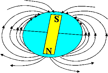
- The Earth has a magnetic field because of its composition, especially because of its core. The core is made up of superheated molten metals under great pressure. As you can recall from lesson 62B-112, heat, pressure, and friction are all methods of generating a voltage. Since the molten metals are in electrical contact with each other, current flows between them, generating a magnetic field. Figure 1 is a representation of the Earth's magnetic field showing imaginary lines of flux leaving at a 90 degree angle from the geographic south pole and entering at a 90 degree angle at the geographic north pole. Although the field at a point, ‘A’, may enter the Earth at an angle, the Earth's field can be resolved into two magnetic components (see Figure 2):
- Horizontal (H) is strongest at the magnetic equator.
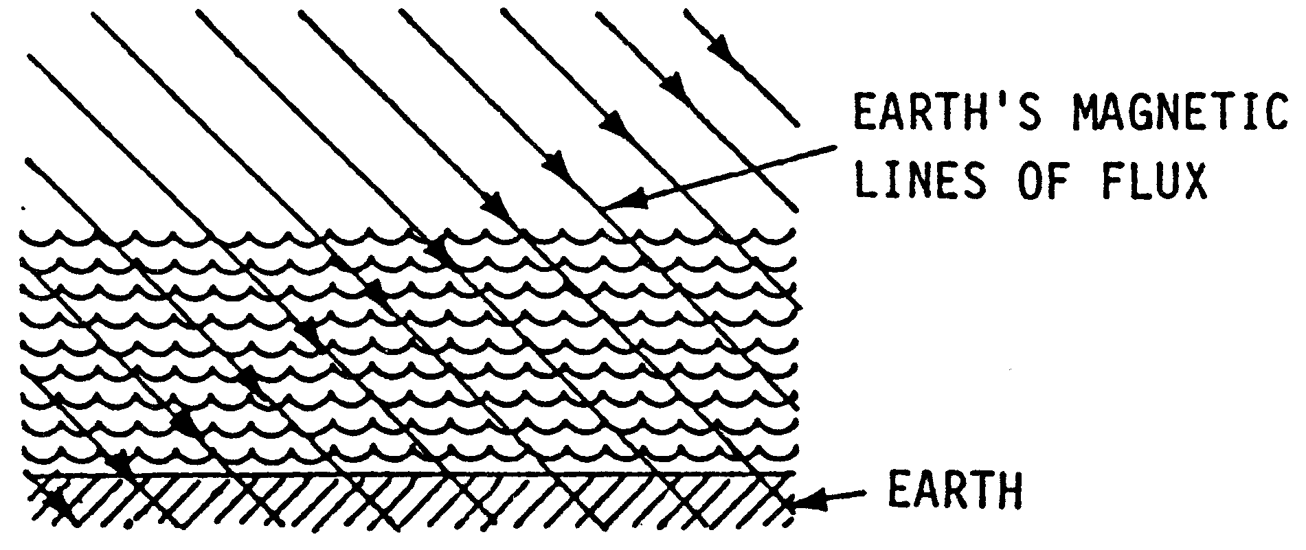
- Vertical (Z) is strongest at magnetic poles.
- Note that the south magnetic pole of the Earth is located near the geographic north pole, and vice versa. Since our magnetic compass’ north pole aligns to the Earth’s magnetic south, we erroneously refer to the magnetic pole near the geographic north pole as magnetic north.
- There is a difference in location between the geographic and magnetic poles. This difference is referred to as magnetic deviation, and is expressed in degrees.
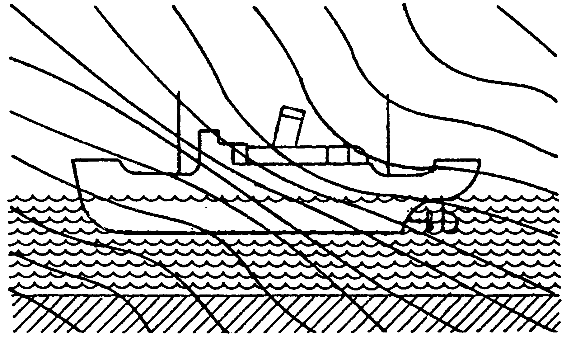
- As you may know, metal objects such as our ships concentrate magnetic fields by providing a low reluctance path for magnetic lines of flux. Reluctance is the opposition a material has to magnetic fields. Due to the ship’s low value of reluctance, this is one way ships distort the Earth’s magnetic field. (See Figure 3)
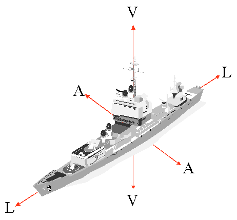
- Ship's permanent magnetic field. (See Figure 4)
- The ship's permanent magnetization is the source of the ship's permanent magnetic field. The process of building a ship in the Earth's magnetic field develops a certain amount of permanent magnetism in the ship. The magnitude of the permanent magnetization depends on the Earth's magnetic field at the place where the ship was built, the material of which the ship is constructed, the methods used to construct the ship, and the orientation of the ship with respect to the Earth's field at the time of building. This permanent magnetic field can be resolved into:
- Vertical permanent field component
- Horizontal permanent field component. It includes the longitudinal permanent field component and the athwartship permanent field component.
- The vertical, longitudinal, and athwartship permanent field components are constant, except for extremely slow changes with time. They are not affected by continuous changes in heading or magnetic latitude.
- Ship's induced magnetic field. (See Figure 5)
- The ship's induced magnetization depends on the strength of the Earth's magnetic field and on the heading of the ship with respect to the inducing (Earth's) field. The ship's induced magnetization, like the ship's permanent magnetization, is a source of the ship's magnetic field.
- The ship is a large metal object (a conductor) moving (relative motion) within a magnetic field. As you will recall from earlier lessons, anytime a conductor is moved within a magnetic field, a voltage is induced into the conductor. The hull plates of the ship are not uniform in construction; therefore different voltages will be induced at different locations in the hull. Since the ship is little more than one giant current path, the differences in electrical potential cause a current flow through the hull, creating a magnetic field that appears about the ship. This induced magnetic field can be resolved into:
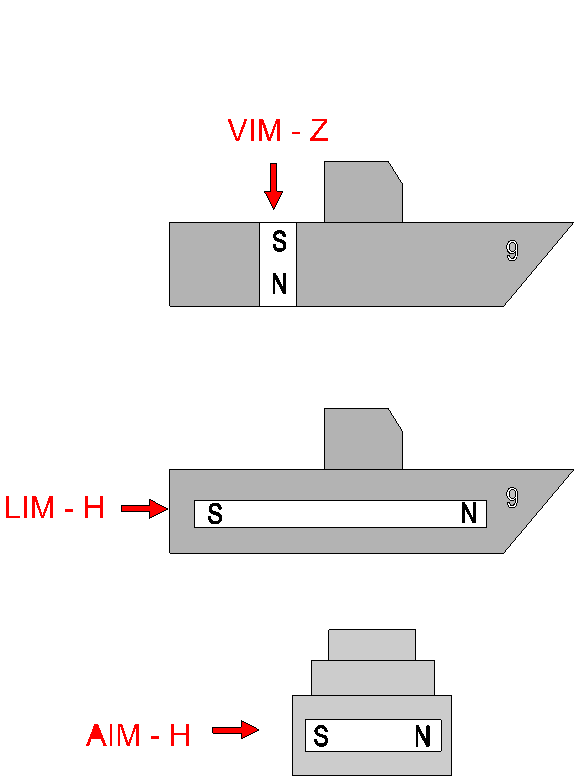
- Vertical induced field component is directed down when the ship is north of the magnetic equator and up when the ship is south of the magnetic equator.
- Longitudinal induced field component. The horizontal induced field component includes the longitudinal induced field component and the athwartship induced field component. The horizontal component of the Earth's field induces a longitudinal or fore-and-aft component of magnetization when on North-South headings.
- The athwartship induced field component. When a ship is on an east heading, a north pole is induced on the port side and a south pole on the starboard side, which is the athwartship component of induced magnetization. The magnitude of the athwartship magnetic field depends on the magnitude of the horizontal component of the Earth's magnetic field at that latitude.
- Degaussing Systems - There are several different types of degaussing systems in the fleet today. The basic differences between them can be characterized as to what type of power supply they use, and what type of control circuitry they use. For example, some units use silicon-controlled rectifier solid-state power supplies (as in the SSM system described below). Other systems use motor generator sets (as in the RM-5 type systems), and still others use a mixture of the two (as in the GM-1A units described below.) An example of two types follows:
- SSM Automatic Degaussing System. This system employs all solid-state technology. It consists of the following components:
- Degaussing coils:
|
Coil |
Changes That Effect Coil Current |
Characteristics |
|
|
|
|
|
M |
Hemisphere |
Positive in Northern
Negative in Southern |
|
FP-QP |
Only when required by magnetic silencing facility |
Value determined after Calibration Ranging and Initial Deperming |
|
FI-QI |
Latitude, heading, and pitch |
Positive in Northerly Heading Negative in Southerly Heading |
|
A |
Heading, latitude, and roll |
Positive in Easterly Heading Negative in Westerly Heading |

- Main coil (M) (See Figure 6) - The M coil compensates the induced and permanent vertical components of the ship's magnetic field (Z zone). It is installed in the horizontal plane at the waterline. As the ship changes hemispheres the coil current polarity must be manually adjusted.

- Forecastle permanent - Quarterdeck permanent coils (FP-QP) (See Figure 7) The FP-QP coil compensates for the longitudinal permanent component of the ship's magnetic field. The FP coil encircles approximately the forward 1/3 of the ship in the horizontal plane at the main deck. QP coil encircles approximately the after 1/3 of the ship in the horizontal plane at the quarterdeck. Any coil current changes require manual adjustment.
- Forecastle induced - Quarterdeck induced coils (FI-QI) (See Figure 7) Located in the same area as the FP-QP coils, they compensate for the longitudinal induced component of the ship's magnetic field. The FI-QI current is proportional to the horizontal component of the Earth's magnetic field along the ship's longitudinal axis. The FI-QI coil current is manually changed, by shifting the "H zone" switch on the switchboard, when the ship's location changes H zones. The degaussing system automatically compensates for heading changes by converting a gyro input signal to a magnetic heading.

- Athwartship coil (A) (See Figure 8) - installed in the vertical plane and extends from the keel to the main deck. It compensates the athwartship induced and athwartship's permanent components of the ship's magnetic field. The A coil current consists of permanent and induced components.
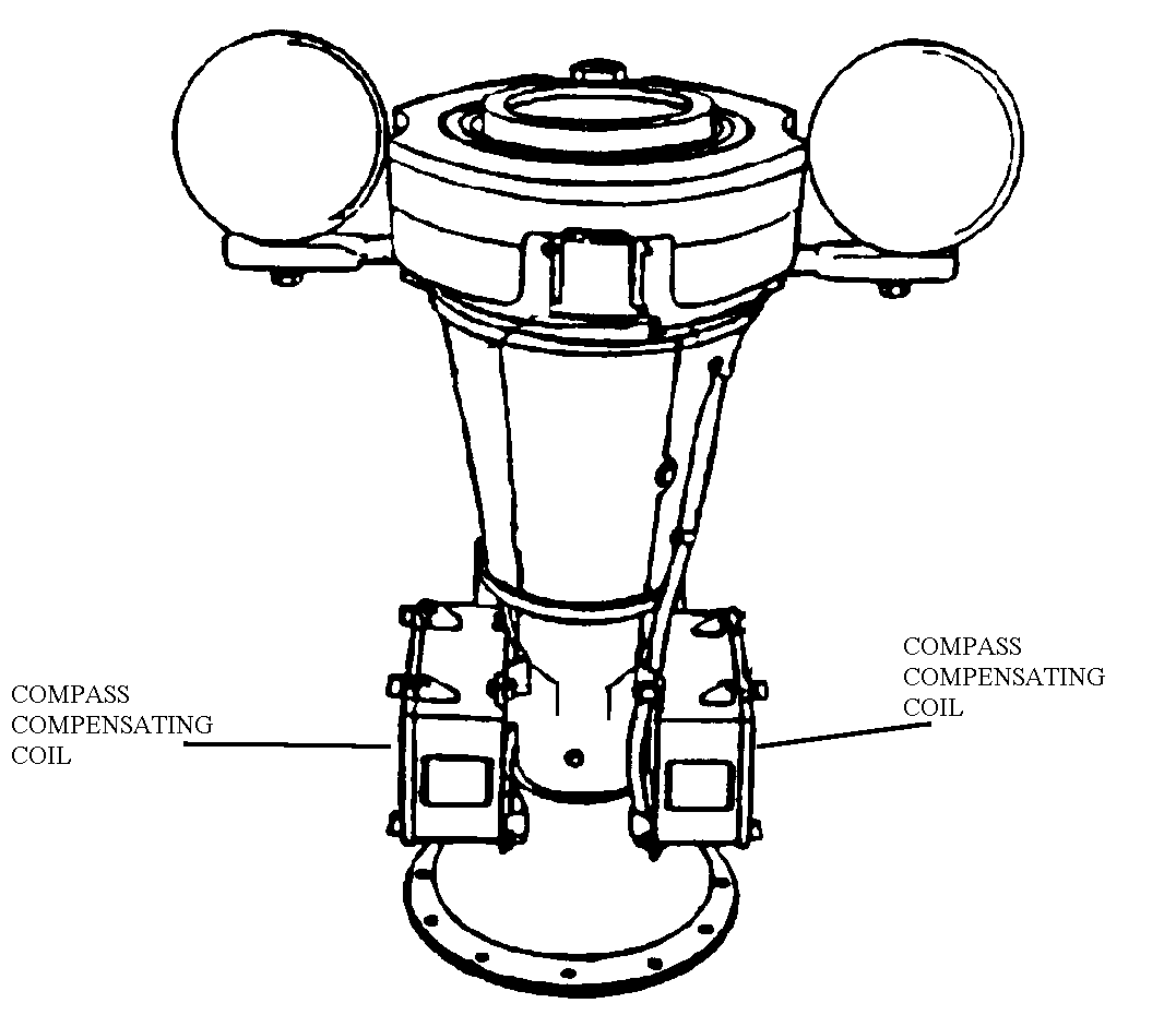
- Compass Compensating Coils. (See Figure 9) Degaussing coils must produce large magnetic fields in order to provide satisfactory degaussing. Unless neutralized in the vicinity of the magnetic compass, these fields make the compass useless for navigation. Compass compensating coils establish a compensating magnetic field that is equal and opposite to the degaussing coil field in the immediate vicinity of the compass.
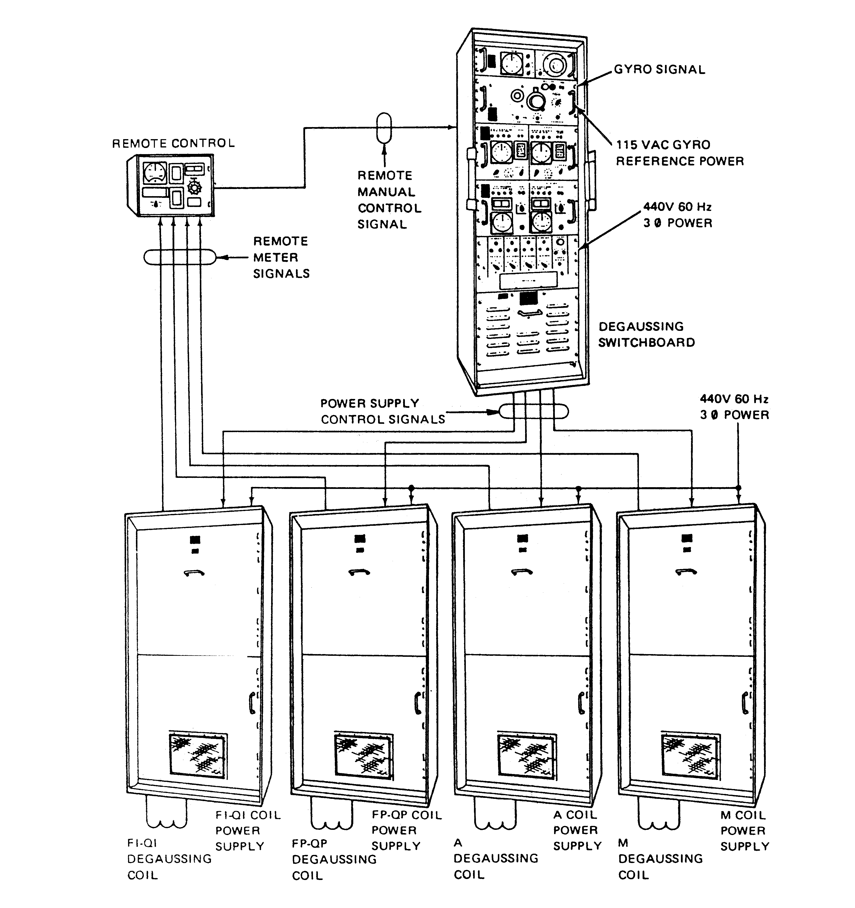
- SSM Degaussing power supplies and controls are contained in five upright cabinets. (See Figure 10) The four power supply cabinets convert 450 VAC, 60 HZ, 3 Phase to 220 VDC for use in the coils. The degaussing switchboard contains all monitoring and controls for automatic and manual operation of the degaussing system.
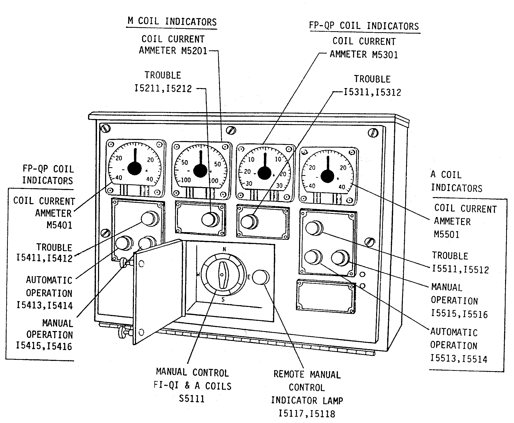
- The Bridge Control Unit allows for remote monitoring and operation. It contains ampere meters, system operation/fault indicating lights and a Cardinal heading switch. The heading switch allows for manual change of polarity and coil current intensity while operating in Remote/Manual. Remote/Manual operation is for emergency use only, and the Quartermaster of the Watch needs to match the Cardinal heading switch with ship's course.
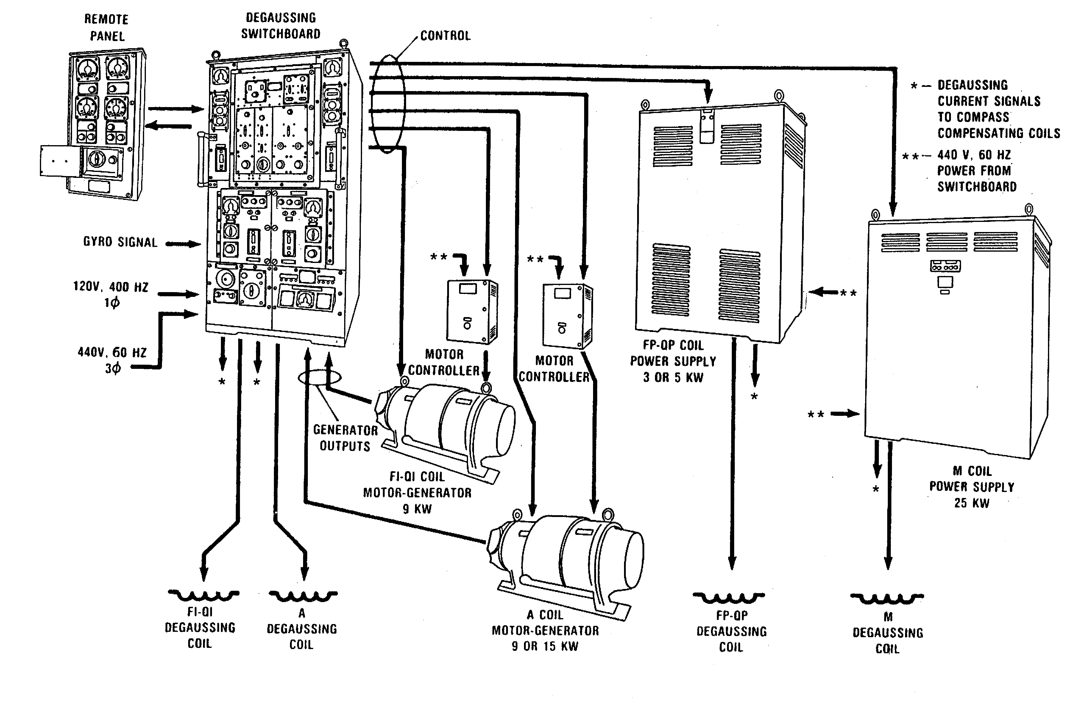
- GM-1A Automatic Degaussing System - Functions exactly the same as the SSM type units except that this system uses two motor/generator sets to supply the coil current for the FI-QI coils and the A Coil and uses magnetic amplifier power supplies to control the FP-FP coils and the M coil. (See Figure 11)
- This type of system uses the same types of coils, the same type of gyro heading information, and the same basic remote control panels (see Figure 12) as any other degaussing system. Again, the only basic differences in degaussing systems (there are at least 9) are the power supply designs and control circuitry designs.
- Preventive Maintenance - Preventive maintenance is extensive for automatic degaussing systems. The degaussing switchboards and remote panels require frequent cleaning and inspection as they are sensitive to heat and dirt. The removal of dirt and dust from automatic degaussing control equipment will facilitate the natural flow of air around the components for heat dissipation. Use of a vacuum cleaner is a safe way to remove dust or dirt. Do not use compressed air.
- Degaussing Folder
- Degaussing folder is an official ship's log and is classified Confidential when filled in. The degaussing folder including the added information which applied to a U.S. Minewarfare ship, may be disclosed to a foreign personnel of magnetic measuring facilities who have national confidential security clearance when and only when specifically authorized by commander mine warfare command or higher authority. Authorization will be considered only when it is necessary for a mine warfare ship to use measurement facilities of a foreign country. It contains the following information:
- Magnetic treatment of the ship
- Instructions for operating the shipboard degaussing system
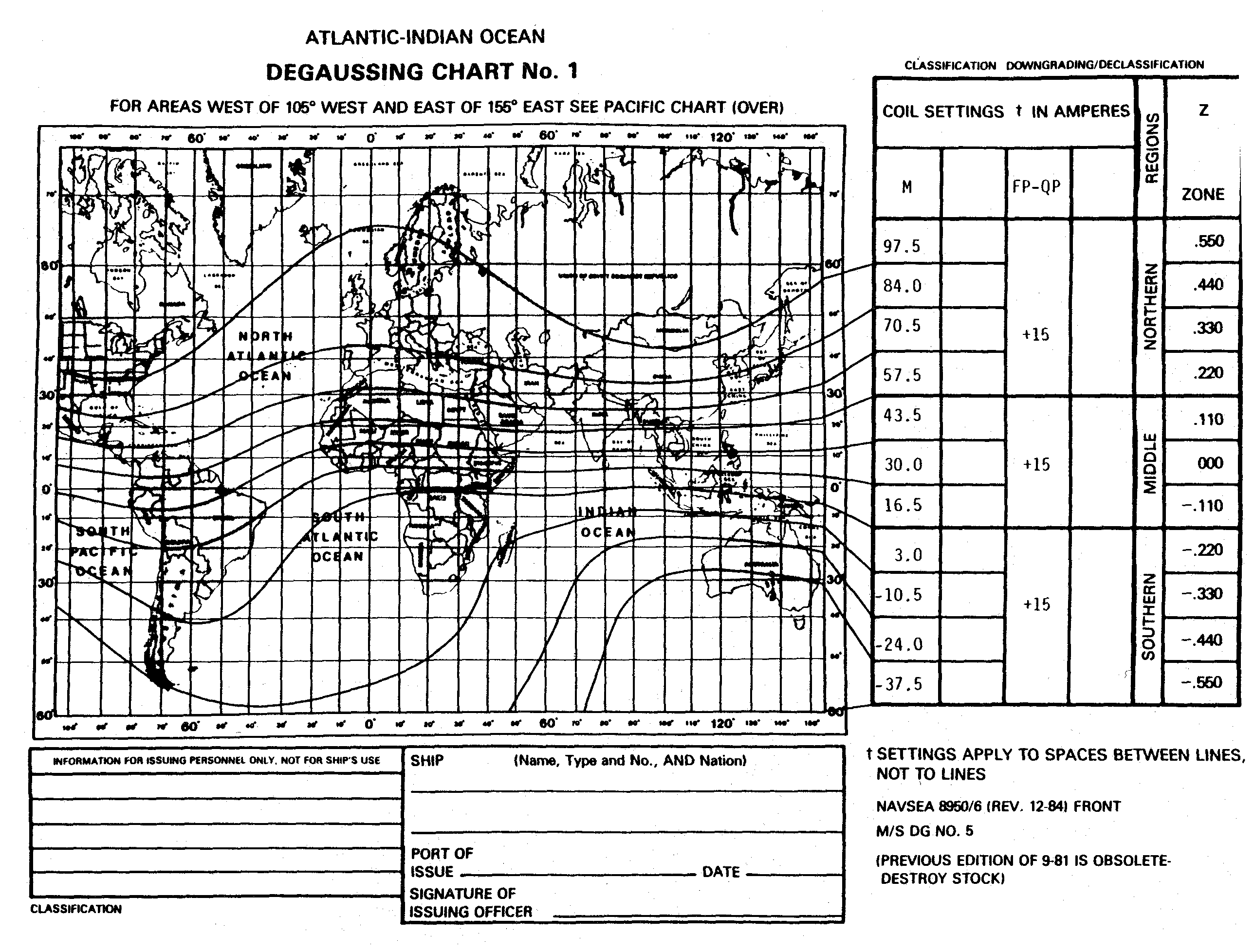
- Degaussing charts with the value of coil settings (See Figure 13)
- Installation information
- Log section showing the details of the action taken on the ship's degaussing system.
- Listing of all USN degaussing facilities and the radio frequencies for contacting them.
- Responsibility:
- The Degaussing Officials:
- The Commanding Officer is responsible for the folder and its general comments. Also, ensures that the folder never leaves the ship unless turned over officially to an authorized magnetic measurement station official.
- Provide all appropriate documents and modify existing documents as required.
- Notify the Commanding Officer of any changes.
- Remove obsolete and outdated material from the folder and to notify the Commanding Officer of any material removed.
- The Navigator:
- Proper system operation.
- Training of personnel in operation of the system.
- Passing the ranges.
- Maintaining proper coil current values as listed in the degaussing folder.
- Custody and updating of the degaussing folder and charts.
- The Chief Engineer:
- Training of personnel to perform preventative and corrective maintenance.
- Documentation for maintenance or corrective action performed.
- Providing the Navigator names of all engineering personnel who require access to the folder for operation and maintenance of the degaussing system.
- The degaussing folder is composed of the following sections:
- Table of contents
- Instructions provides a supplement to the technical manual for operation of the degaussing equipment. Explains when, how, and why magnetic field measurements and treatments are to be conducted. Provides instructions for controlling shipboard magnetic material and for inspections to maintain minimum stray fields.
- Reports of Magnetic Condition
- Report of Normal Magnetic Field tells whether ship is magnetically safe and is conducted quarterly. The report is prepared by Magnetic silencing personnel and sent to the ship.
- Charts: This section contains the H and Z zone settings and current requirements for the ship. Provides the course correction diagram for manual operation. There are two charts provided to cover the entire globe.
- Installation: It gives a complete record of degaussing coils installed, number of turns, specifications on different coils, and type of controller. The certificate of any modification is filled in this section.
- Logs
- Record of all degaussing action. This provides a chronological record aboard the ship of its degaussing actions. For instance, corrective maintenance, receipts of new forms and installation of records for degaussing. Entries are made by ship's personnel and range officials.
- Facilities list all U.S Navy degaussing facilities and charts showing location (not for navigation).
- Papers- It is used for filing any papers concerning degaussing that do not fit in one of the other sections.
- Ranging
- The degaussing range is responsible for measuring, analyzing, and maintaining records of magnetic field data. The degaussing range measures the effectiveness of the ship's degaussing system. The ship will run the range for calibration and checking signature. Every new ship will run the degaussing range for calibration. This will determine the initial ship's signature and degaussing coil current settings. This process determines the systems' reliability and accuracy.
- Check ranging usually occurs during a ship's entry or leaving port. After passing over measuring equipment located at or near the bottom of the channel in which the ships travel, the ship receives a report of its magnetic characteristics. If the strength of its magnetic field exceeds a safe operational level, the ship is scheduled to report for calibration ranging.
- Calibration ranging requires the ship to make a number of passes over the range while its shipboard degaussing coils are being adjusted and calibrated from information supplied from the range hut. When the new settings for the degaussing coils have been determined, new degaussing control settings are placed in the degaussing folder.
- If the ship is unable to compensate adequately for its magnetic field because of excessive permanent longitudinal or permanent athwartship magnetization or an irregular permanent vertical magnetization, the ship is scheduled to report for deperming.
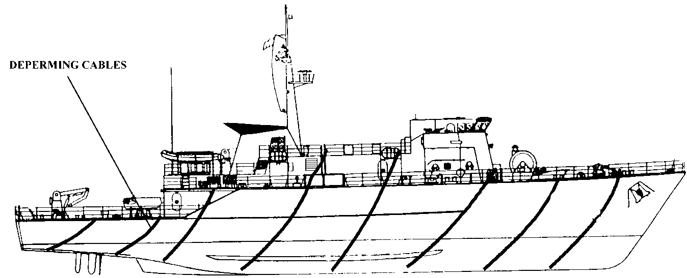
- Deperming (See Figure 14)- The purpose is to reduce permanent magnetization and bring all ships of the same class into a standard condition. Deperming is essentially a large-scale version of demagnetizing a watch. It is normally accomplish only once in a ship's life or when major structural changes occur during overhaul. Before deperming begins, all magnetically sensitive equipment is removed from the ship. The deperming process is conducted at a specially designed pier. Ship's force rigs and unrigs the cables that are wrapped around the ship. The process requires the cables to be energized by a high DC current for specific duration and magnitude. Then a reverse polarity DC current of the same duration and magnitude is passed through the cables. This process is repeated reducing the duration and magnitude until the ship is depermed.
- The range and calibration reports are filed in the degaussing folder. Failure to pass check ranging requires the range personnel to enter a recommended course of action entered in the range report. The range personnel determine what corrections are required to bring the system into specifications.
 Engineering Training
 Engineering Training


