 Deck Officer
  Deck Officer
 INFORMATION SHEET
WELL DECK/STERN GATE OPERATION AND SMALL BOAT CONSIDERATIONS
Information Sheet 1.4
INTRODUCTION
Assault landing craft range in size from about 36 feet to 135 feet in length. Landing craft are specifically designed and constructed to support the surface ship-to-shore movement of troops, cargo, and vehicles. Most landing craft are attached to the Assault Craft Unit of the Naval Beach Group, which provides LCMs, LCUs, and LCACs for assault transport and general lighterage duties. It is imperative that the assault boat coxswain understand and have complete familiarity with the theory of boat handling and the procedures utilized to operate the craft in a safe and efficient manner. It is also important for the First Lieutenant/Deck Officer to understand the operations and safety precautions associated with stern and well deck operations.
REFERENCES
(a) COMNAVSURFLANT/COMNAVSURFPACINST 3340.3 (B)
(b) NAVSHIPS TECHNICAL MANUAL, CHAP 584
(c) COMNAVSURFLANT 3401.1 (B)
(d) NWP 3-02.4
(e) Safe Engineering and Operations Manual for Landing Craft Air Cushion (SEOPS) Vol III
INFORMATION
A. EMBARKING AMPHIBIOUS ASSAULT VEHICLES (AAVs)
1. Embarkation into the well deck may be accomplished during the following conditions:
a. When the ship is at anchor
b. When the ship is lying to or is underway with bare steerageway
c. When the ship is pierside
Approach Control Officer.
3. Embarkation procedure
a. The receiving ship ballasts to a depth of 3-6 feet over the sill (the base of the well deck or tank deck where the stern gate sits when stowed) and a dry well forward for AAV embarkation.
b. The receiving ship calls in AAVs using signal flags or lights from the control station located aft on the main deck. Control lights and flags are used during day operations, while control lights and red/green wands are used during night operations.
(1) Green light or green flag: "Ready to receive AAV"
(2) Red light or red flag: "Not Ready to receive AAV"
c. The operators drive their AAVs aboard front end first.
(1) AAV drivers are guided by wand signals from the Petty Officer in Charge (POIC). The POIC directs the AAV into the well until the AAV is grounded.
(2) When the AAV is grounded in the proper position, the POIC signals the AAV to shift to track drive and pivot 180 degrees.
(3) The AAV then backs into the parking area.
d. As soon as the AAV is turned and backed or towed clear of the well deck, another AAV will enter the well deck and the embarkation procedure will continue.
e. When AAVs are stopped, AAV crewmen secure power to their vehicles. All personnel remain onboard their vehicle until embarkation is complete.
B. SECURING THE AAVs AFTER EMBARKATION
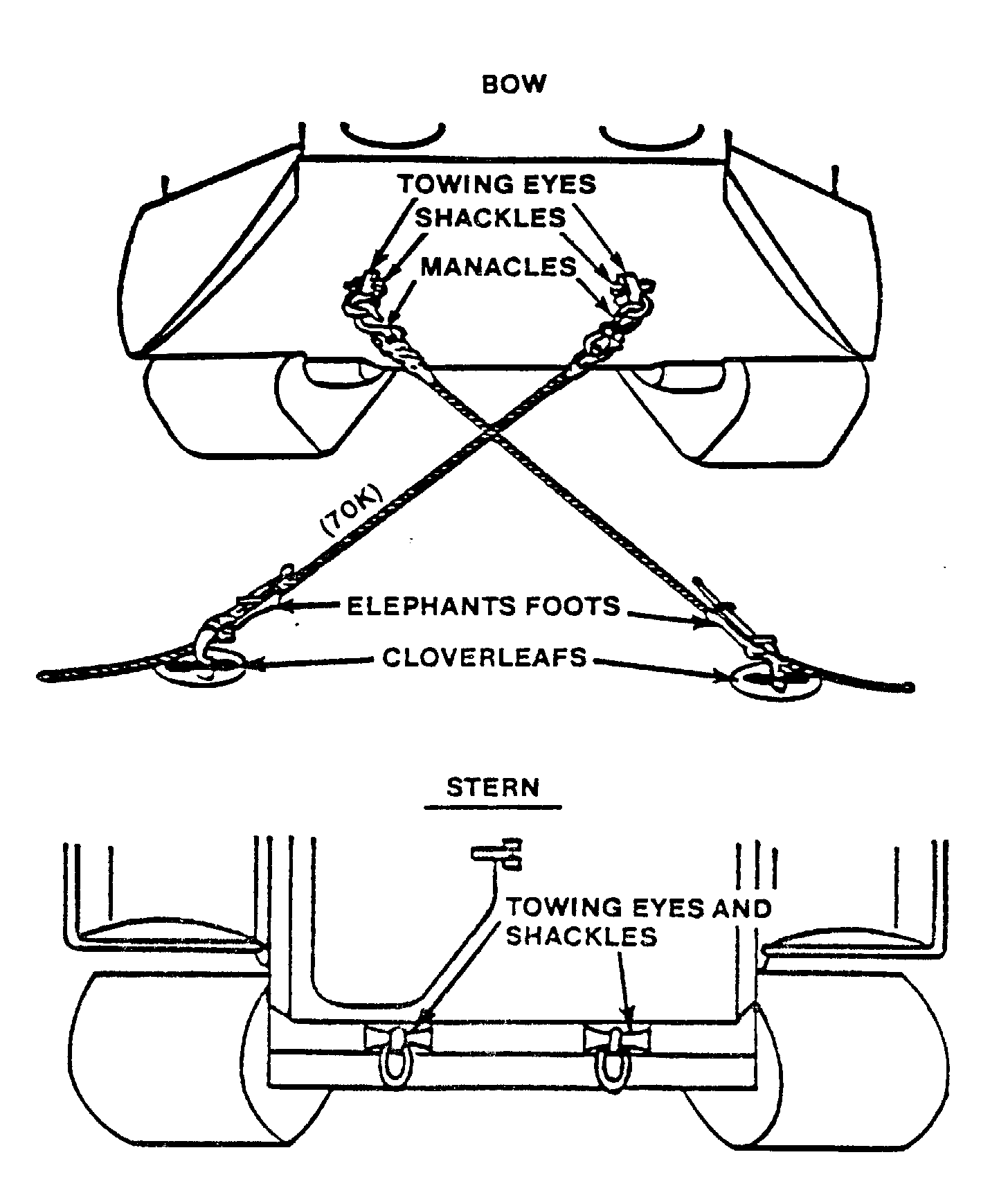
1. Securing the AAVs to the well deck
a. The ship will provide appropriate lashing/shoring/dunnage to the vehicle crew for securing the vehicles. The tank, AAV, or vehicle crew is responsible for securing their own equipment/vehicle(s) under the supervision of ship's force personnel.
b. The ship is responsible for making sure that the vehicle(s) is/are properly secured.
c. Lashing assemblies will never be attached to tracks, sprockets, or idler assemblies, nor will tracked vehicles be secured by passing lashing around the tracks.
2. Physical security of the AAVs
a. The embarked unit is responsible for providing an integrity/security watch for its equipment.
3. Test running the AAVs
a. The AAV unit commander must contact the ship's designated representative when desiring to test, operate, or move an AAV.
b. The ship's representative will make sure that all cognizant ship's personnel are notified of the intended AAV operations and that all safety precautions have been taken.
4. Fuel Safety
a. AAVs use diesel fuel but can use JP-5 or F-76.
b. Although bulk Petroleum Oil and Lubricants (POL) are classified as Landing Force Operational Reserve Material (LFORM), they may be consumed in training or in operations. AAV units drawing bulk POL during exercises are required to provide the ship with appropriate documentation within ten days.
c. Permission must be obtained from the ship's OOD (underway) or CDO (in port) prior to refueling AAVs or transferring fuel from one AAV to another.
d. Proper ventilation must be maintained to the well fueling area to expel all fumes.
e. The smoking lamp shall be secured on the well deck.
f. To reduce the danger of ignition of fuel from a static spark, the filling hose nozzle is provided with a grounding wire.
g. The number of personnel on the vehicle should be kept to a minimum.
C. PREPARING FOR AN AAV LAUNCH
1. Before launching the AAVs, close all hatches, ramps, and vents to avoid sinking the AAVs. The plenum air inlet grill should also be secured.
2. Warm-up AAVs in groups of not more than three to ensure engine exhaust fumes remain within capacity of well deck exhaust blowers.
3. Embark the troops
a. Embark troops 20 to 40 minutes prior to launch.
b. When crew/troops are embarked, AAV unit commander collects manifests from all AAVs and turns them over to the First Lieutenant/Combat Cargo Officer.
D. DEBARKATION OF THE AAVs
1. The procedure is the same whether the ship is underway, at anchor, or lying to.
a. Set Condition 1A (1A/modified 1A is set well deck operations and involved additional watchstanders on the bridge and in CIC as well as manning well deck and ballast control stations) and ballast to approximately one foot at the sill.
b. Caution: It is absolutely essential that the stern gate be properly positioned.
(1) Best position is at 0 degrees (horizontal) to - 3 degrees (below horizontal).
c. AAV unit commanders have the responsibility for coordinating with the ship's personnel to make sure that the stern ramp will be positioned at the correct angle and that positive launch control procedures, to include both launch and abort signals, are clearly understood by all hands.
d. AAVs will be launched in single column or in pairs. If launched in pairs, a minimum clearance of three feet must be maintained between vehicles.
e. Underway launch of AAVs is safe at any speed up to 21.5 knots.
f. Generally, it is easier to control the AAVs if launched while traveling at faster speeds.
(1) At speeds over ten knots, AAVs may be launched at five second intervals.
(2) The launch intervals should be increased to at least 10 seconds if the ship's speed is less than 10 knots.
g. It is difficult for the AAV Unit Leader to determine when the last AAV in his column has been launched. This problem can be alleviated by using a prearranged signal from the ship.
2. The CO of the ship must determine the launch interval which is determined by:
a. The ship's speed at the time of the launch (ordered by the CO)
b. The width of line of departure (LOD)
c. The width of area to be assaulted
d. The number of AAVs to be launched
E. EMERGENCY PROCEDURES FOR ASSISTING DISABLED OR SINKING AAVs
1. Waterborne AAV assistance procedures
a. It is the responsibility of the ship launching AAVs to ensure that a safety boat is available prior to launch.
b. A safety boat will be present in the water whenever AAVs are to be launched and/or are waterborne.
2. Procedures when AAVs are disabled
a. In fair weather, a safety boat or a rescue vehicle will come along the port side of the AAV and will position itself alongside the disabled vehicle with hand tended lines.
b. Under no circumstances will the rescue boat be made fast to the disabled AAV.
c. Disabled vehicles will be emptied of personnel prior to being taken in tow.
d. In foul weather or when the assisting vehicle is unable to come alongside the disabled vehicle, the rescue vehicle will stand by on the windward side of disabled vehicle. Passengers from the disabled vehicle will swim to the rescue vehicle in small groups for recovery by the crew of that craft.
3. Towing the AAV
a. Towing procedures
(1) As a general rule, a disabled AAV should only be towed by another AAV.
(2) Disabled AAVs should be towed to the high water mark on the beach before the stern towing cable is detached.
(3) An LCM may be used for towing if an AAV is unavailable.
F. WELL DECK SHIPS' STERN GATES (LHD, LPD, and LHA generic)
1. Purpose
a. To provide a ready access to the well deck so that waterborne operations may be conducted.
2. Operation
a. Gates are raised and lowered by hydraulic operating equipment.
(1) Components of power unit
(a) Reservoir
(b) Two main pumps
(c) Two hand pumps for use if electrical power is lost or if there is a pump failure
(d) Hydraulic valve block containing directional, check, and counterbalance valves
(e) Suitable piping and valves to connect components
(2) Hydraulic Cylinders System
(a) Supplies pressurized hydraulic fluid for operation of hydraulic rams that open and close the gate.
(b) Two electric motors drive constant volume pumps which draw fluid from a reservoir and suction strainers. Either motor can drive either pump.
(3) Hand-powered operation
(a) Used in the event that the electrically driven pumps fail
(b) The difference between the hydraulic system and the alignment for hand powered operation is in the flow path from the service tank to the manifold.
(1) For each pump there is an isolation valve (on the outlet of the relief valve) for pump discharge and a relief valve return line isolation valve.
(2) For hand powered operations, both of these valves must be closed.
(3) The pump discharge valves are mechanically interlocked to power cut-off switches for the pump motors.
b. Emergency raising and lowering of the stern gate is accomplished using a series of chain falls and block and tackle systems in place of the hydraulics.
3. LPD Stern Gates
a. Operation of upper and lower stern gates - Hydraulic system provides hydraulic power to operate four cylinders for opening and closing upper and lower stern gates.
b. Stern gate interlocks - stern gates are electrically interlocked, preventing the lower gate from being opened before the upper gate is fully open or the upper gate from being closed before the lower gate is fully closed.
c. Stern gate positive lock - Mechanical latch on both upper gate cylinder assemblies positively locks upper gate in open position.
d. Safe operating conditions - the system can be operated safely in any sea state up to and including sea state three at speeds not to exceed fifteen knots.
e. Emergency lifting procedures
(1) Emergency procedures are required in order to close the stern gate if both the normal and alternate systems fail or if a rupture occurs in the pressurized hydraulic system while the stern gate is in the open position.
(2) If underway or able to get underway, ballast to a depth that reduces the pounding of the gate on its stop. As soon as it is ready, get underway and proceed as below.
If there is some delay in getting underway, ballast to a depth that reduces the pounding of the gate on its stop. As soon as ready, get underway and proceed as below.
(3) Once the gate is hydroplaning, deballast and connect the emergency lifting pendants to the gate. Use two men in safety harnesses, kapok life jackets, and tended safety lines on stern gate to connect emergency rigging.
4. LST Stern Gates
a. Characteristics
(1) Gates are vertical steel structures of various configurations and sizes.
(2) Single closure stern gates that are hinged at bottom and rotate down and away from the stern.
b. Function
(1) Operated by hydraulic cylinders or capable systems wound by winches or capstans.
(2) Use of winch:
(a) Double drum is used to spool on wire rope
(b) Two wire ropes (one on each side of the gate) are used to raise and lower gate and are spooled simultaneously.
(c) Winch assembly is provided with a torque-limiting coupling between the electric motor and the gear reducer. This coupling protects the system from overload and prevents excessive loads on the wire rope.
(3) Local and remote controls:
(a) Located so the operator can observe the stern gate operation
(b) Are push button switches that raise, lower, and have emergency run features
(c) Have handcranks available for manual operation of the winch in case of power failure
(4) Capstan winch, when used, has a multipart rope guided through the stern chocks to each side of the stern gate to a fitting at or near the top of the gate.
5. LHA Stern Gates
a. The LHA Stern gate consists of a upper and lower closure. The closures are raised or lowered by two hydraulic two winding drum winch assemblies.
b. Retractable stops lock the stern gate into the fully open or fully closed position.
c. The LHA stern gate provides a 76 foot wide and 28 foot high opening to allow landing craft and amphibious craft to enter and exit the well. The weight of the stern gate is 95 tons.
6. LSD Stern Gates
a. The LSD stern gate is electro-hydraulically controlled at the operators station located on the port wing wall. When the open button is depressed, fluid flows through a series of valves and ports into a cylinder allowing the gate to open. When the gate is in a fully open position (resting on the stops). The button is released and the gate spool goes to a neutral setting.
b. Securing the stern gate. The opening process is reversed and the gate is lifted to the closed position. When the gate reaches the fully closed position the close button is released. The
hydraulic system is set to a neutral position and hand manipulated locking mechanisms are put into place to secure the gate.
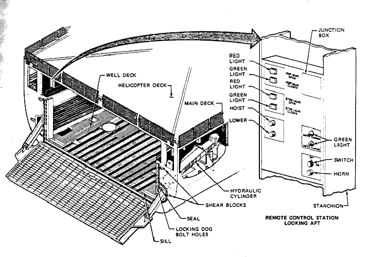
Figure 1.4-2 LSD 41 Class Stern Gate
G. STERN GATE MARRYING AN LCU TO AN LST
1. Special Provisions - LCU Stern Gate Marriage
a. Limited by sea state. Must be in a calm sea or inner (sheltered) harbor.
2. Planning and preparation for LST
a. Ensure that power is available to all winches and gear.
b. Conduct phone checks on all S/P circuits to be used.
c. LST provides:
(1) 600 feet of 6 inch nylon (snaking line)
(2) Two 6 inch manila or 5 inch nylon positioning lines 300 feet long
(3) One 7/8 inch wire strap 15 to 20 feet long with a soft eye in both ends
(4) Two 1.5 inch screw pin shackles (one slotted to use in the top of the rhino horn)
(5) Two heaving lines for each positioning line and snaking line
(6) One electric megaphone
(7) One portable cutting torch
(8) 18 inch snatch block with bulb hook (be prepared to provide to LCU if requested)
(9) Use fenders to protect stern gate ramp gasket.
3. Procedure for marrying an LCU to an LST
a. Receiving ship makes initial preparations
(1) Set Condition 1A
(2) Lower stern gate
(3) Using flags or lights, signal LCU to begin its approach
(a) Daylight - 36" x 36" green flag on main deck aft
(b) Night - green light on main deck aft
b. LCU lowers its bow ramp and begins its approach in a slow, controlled manner.
c. LST lowers stern anchor until bending shackle is below the water's edge.
d. LCU rigs 18 inch snatch block to cloverleaf on deck.
e. Upon signal, LCU approaches the stern.
f. LCU keeps the ramp at sufficient height to clear the stern gate and rhino horn.
g. LCU stops approximately twenty yards from stern gate.
(1) One from the starboard stern chock to the port bitts of the LCU
(2) Other from the port stern chock to the starboard bitts of the LCU
(3) When the lines are secured, the LCU keeps its engines going astern.
i. Snaking line
(1) LST passes the snaking line from the tank deck to the LCU with a heaving line and messenger.
(2) LCU passes the snaking line through the snatch block and through the rhino hole, then bends it on to the heaving line and passes it back to the LST.
j. LST secures the snaking line to a 15 - 20 foot pendant (7/8 inch wire strap) that is shackled to the top of the rhino horn.
k. LST heaves around on the snaking line and the bow positioning lines.
(1) Pulls bow ramp of the LCU to the stern gate using bow positioning lines to align the LCU ramp with the stern gate.
l. LCU should be ready to lower bow ramp on signal from the POIC of the tank deck.
m. LST raises and properly secures the rhino horn.
n. LST slacks off the stern gate hoisting cables and secures the cables against the transom.
o. Once the LCU ramp is fully seated around the rhino horn, bow positioning lines are shifted to opposite bitts on the LCU to clear the stern gate opening.
p. The marriage is complete.
4. Breaking the Marriage on an LST
a. Retrieve the wire pendant from the rhino horn.
b. After the pendant is removed, the LST should have the LCU cast off the bow positioning lines which will then be retrieved by the LST.
c. When directed by the POIC of the tank deck, the LCU will raise its ramp and clear the rhino horn and the stern gate under its own power.
d. LST will then clear the hoisting wires and raise the stern gate.
5. Stern gate marrying an LCU with an LSD/LPD
a. Upon starting the operation, the ship will set Condition 1A, ballast to 1-2 feet from the sill, and lower the ship's stern gate to the stops.
b. Once the marriage blocks are in place, line handlers are in position, and the ship is ready for the evolution to begin, the ship will indicate by the use of flags or a light that it is ready to begin the stern gate marriage; the LCU may begin its approach.
c. The LCU will lower its bow ramp and make its approach on the stern of the ship in a slow, controlled manner.
d. As soon as possible, the ship will pass positioning lines from the port and starboard wingwalls of the ship to the LCU and fairlead the positioning lines to the capstans located on each wingwall.
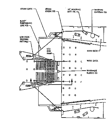
e. The LCU uses engines in conjunction with the ship's positioning lines to bring the bow of the LCU up against the marriage blocks.
f. Once the LCU is in position against the marriage blocks, the ship may pass the marriage chains to the LCU. The ship takes the slack out of marriage chains by use of turnbuckles, taking an even strain on both chains.
g. The LCU will use engines as required to hold the LCU ramp in the marriage blocks. At this point, embarkation or debarkation into the well deck can begin.
Figure 1.4-3 Stern Gate Marriage LCU/LSD
6. Breaking the Marriage on a LSD/LPD
a. Upon the completion of off-loading/onloading, the ship will cast off the marriage chains (if used) and positioning lines. As the LCU backs clear of the ship's stern, the LCU will simultaneously raise its ramp and proceed as instructed.
7. Procedure for marrying an LCU to and LHA
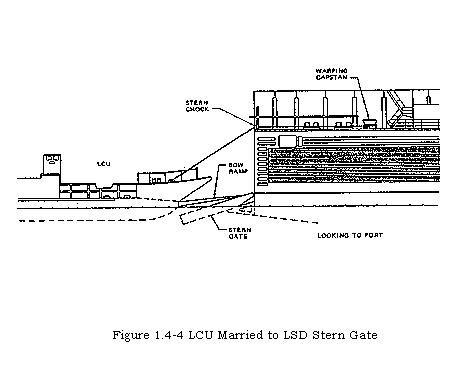
7. Stern gate marrying an LCU with an LHA
a. Upon beginning the operation, the ship will set Condition 1A, lower the stern gate, and ballast to the sill.
b. Once the line handlers are in position and the ship is ready for the evolution to begin, the ship will indicate by the use of flags or light that the ship is ready to begin stern gate marriage and the LCU may begin its approach.
c. The LCU will lower its bow ramp to approximately 90 degrees and make its approach on the stern of the ship in a slow controlled manner.
d. When the craft bow ramp is approximately 10-15 feet inside the well, the ship will pass the bitter end of the positioning lines to the LCU.
e. Positioning lines are attached to the well deck of the LHA by the deck padeye assembly and are tended by the craft.
f. The craft will slowly back out of the well while checking its positioning lines and lowering the bow ramp. Approximately 3-5 feet from the marriage blocks the positioning lines will be secured.
g. The LCU will continue backing, keeping an even strain on the positioning lines until the bow ramp drops into the permanent marriage block.
h. The craftmaster will then maneuver engines ahead to maintain the ramp against the block.
i. Once in this position, the ship will pass marriage chains to the LCU and take the slack out by use of turnbuckles. An even strain is taken on both chains.
j. At this point loading or unloading may begin.
8. Breaking the Marriage on an LHA
a. Upon completion of loading or unloading the ship will cast off the marriage chains; the LCU then casts off its positioning lines while simultaneously backing clear of the stern and raising its bow ramp.
H. BOATS AND BOAT HANDLING
1. Boat types
a. Landing Craft Personnel Large (LCPL)
(1) Characteristics
(a) Length - 36 feet
(b) Beam - 13 feet
(c) Hoisting Weight - 17,500 lbs
(d) Cargo Capacity - 2,700 lbs
(e) Personnel Capacity - 12
(f) Crew - 1 Officer, 3 Enlisted
(g) Speed - 19 knots
(h) Propulsion - 8V71T1
(2) Utilization
(a) Boat Group Commander
(b) Safety Boat
(c) Liberty Launch
b. Landing Craft Mechanized Six (LCM-6)
(1) Characteristics
(a) Length - 56 feet
(b) Beam - 14 feet
(c) Hoisting Weight - 56,000 lbs
(d) Cargo Capacity - 68,000 lbs
(e) Personnel Capacity - 120
(f) Crew - 1 Officer, 4 Enlisted
(h) Speed - 9 knots
(2) Utilization
(a) Salvage
(b) Landing Cargo
(c) Personnel Transportation
(d) Ship to shore movement
c. Landing Craft Mechanized Eight (LCM-8)
(1) Characteristics
(a) Length - 74 feet
(b) Beam - 21 feet
(c) Hoisting Weight - 131,326 lbs
(d) Cargo Capacity - 120,000 lbs
(e) Personnel Capacity - 225
(f) Crew - 4 Enlisted
(g) Speed - 9 knots
(h) Propulsion - 12V71 Detroit Diesel
(2) Utilization
(a) Cargo and personnel ship to shore
(b) Vehicles ship to shore
d. Landing Craft Utility (LCU)
(1) Characteristics
(a) Length - 135 feet
(b) Beam - 29 feet
(c) Hoisting weight - 190 tons
(d) Cargo Capacity - 360,000 lbs
(e) Personnel Capacity - 350 - 400
(f) Speed - 11 knots
(g) Propulsion - 12V71
(2) Utilization
(a) Ship to shore movement of:
Personnel, Cargo, and Vehicles
(b) Deploying Amphibious Assault Bulk Fuel System
e. Landing Craft Air Cushion (LCAC)
(1) Characteristics
(a) Length - 88 feet
(b) Beam - 47 feet
(c) Hoisting Weight - 169 tons
(d) Cargo Capacity - 120,000 lbs
(e) Personnel Capacity - 24
(f) Crew - 5 Enlisted
(g) Speed - 40+ knots
(h) Propulsion TF-40B Gas Turbine Engine (2)
(2) Utilization
(a) Ship to shore movement of:
Personnel, Vehicles and Cargo
2. Boat handling theory
a. Side force
(1) In addition to thrust, a rotating propeller produces a side force.
(a) When the engines are on ahead bells, the side force is small and the rudder will make up for any effect.
(b) When backing, this force tends to walk the stern sideways in the direction of motion of the upper portion of the propeller. The stern will walk to port (or starboard) depending on the direction of screw rotation.
(c) On single screw craft, such as the LCPLs and LCVPs, the side force will have a strong effect when backing.
(d) On twin screw craft, such as LCMs and LCUs, the side force will be canceled out if both engines are backing. The screws rotate in opposite directions and the
side forces cancel.
(e) When the engines are set in opposition, one ahead while the other back, the side forces add up and contribute to the overall twisting effect.
b. Wind effects
(1) Tends to push a boat downwind.
(2) Effects differ on bow and stern, depending upon where the greater amount of freeboard.
(a) Differs in an assault boat depending on the cargo load.
(3) The wind will force the boat to rotate around a pivot point that changes with the status of the boat. The pivot point is:
(a) One third the way back from the bow when moving ahead.
(b) In the center when dead in the water.
(c) On the rudder post when backing.
(4) With greater freeboard aft of the pivot point, the wind tends to drive the bow into the wind.
(5) With greater freeboard forward of the pivot point, the wind tends to drive the bow downwind.
c. Current effects
(1) Current effects are similar to wind effects, except that for a given velocity, the effect of current is much greater. This is due to the greater density of the medium.
(2) Long shore current runs parallel to the beach and can serve to push landing craft approaching the beach off its mark.
(a) It can also pose a broaching problem to a beached craft. The steeper the beach gradient and the greater the long shore current, the greater the probability of broaching.
(3) Rip current runs perpendicular to the beach and significantly reduces headway approaching the beach.
d. Surf
(1) Spilling surf
(a) Occurs in areas of low wave velocity and gentle beach gradients.
(b) Wave energy released slowly over a wide area.
(c) Has little effect on boat handling.
(2) Plunging surf
(a) Occurs in areas of moderate wave heights and low to moderate wave velocities.
(b) Wave energy released rapidly over a wide area.
(c) Tends to drive a landing craft toward the beach with surfing effect.
(d) If the wave height exceeds freeboard at the stern, landing craft may be swamped.
(3) Surging surf
(a) Occurs in areas of high waves or swells and steep beach gradients.
(b) Wave energy is released suddenly in near vertical area.
(c) Effects on landing craft is great, with high probability of severe damage to landing craft on the beach.
e. Mooring alongside a pier, causeway, or stern gate.
(1) All pier approaches should be made as slow as possible to maintain control of the craft in given wind and current conditions.
(2) Windward approach
(a) Approach pier at approximately 20 degree angle.
(b) When craft is approximately a boat length away from the pier, turn rudder away from pier.
(c) When craft is parallel to pier, back down, bring craft dead in the water.
(d) Put over bow and stern lines.
(3) Leeward approach
(a) Approach pier at about a 30 degree angle.
(b) When within line throwing distance, put over bow line and idle craft or use ahead slow if the wind is strong. Use rudder if necessary to avoid striking pier.
(c) With bow line secured, twist away from pier to bring stern towards pier.
(d) Put over stern line, heave in, and secure.
(e) Twist bow toward pier, heave in on bow line, and secure.
f. Getting underway from a pier, causeway, or stern gate.
(1) Cast off stern line; take in slack on bow line.
(2) With rudder toward pier, kick engine ahead in single screw; twist toward pier with twin screw craft.
(3) When stern is well clear of pier, cast off bow line and back straight out from pier.
g. Wet well operations
(1) Approaching the well
(a) Craft approaches center of well at a slow speed with positive control and constant forward motion.
(b) Two line handlers, one at bow and one at the stern, will be in stand-by position to receive positional mooring lines.
(2) Entering well
(a) Upon entering well, positioning/mooring lines will be attached to craft and commanding officer of transport ship will assume operational control of the craft.
(b) Coxswain should be aware that in shallow water of well deck, effectiveness of rudder will be reduced.
(3) Exiting well
(a) Ensure engines are not started until there is sufficient depth of water in well to properly cool engines.
(b) Line handlers stand by for positioning/mooring lines.
(c) Craft does not commence backing out until directed by Well Deck Officer.
h. Beaching and retracting
(1) Beaching
(a) Upon entering surf zone, the craft should turn perpendicular to the beach and remain so until exiting surf zone.
(1) Long shore currents tend to push the stern of the craft down current. Some rudder may be required to hold craft perpendicular.
(2) As water shallows, rudder effectiveness will be diminished and more paddle may be required to remain perpendicular.
(b) Craft with stern anchors should drop anchor 300-400 feet from where expected to ground out.
(c) Prior to beaching, safety precautions should be observed.
(1) Rolling stock has emergency brake set, driver in driver's seat riding brake, and engine running in preparation for debarkation.
(2) Coxswain calls "Stand by to touch down" and ensures no personnel are standing in front of rolling stock.
(d) Once beached, coxswain holds position with engines forward using rudder as necessary to maintain perpendicular orientation to the beach.
(2) Retracting
(a) Coxswain will begin backing when stern is riding crest of a wave. Keeping bow pointed towards the beach until clear of surf zone.
(1) Use of the screws is more effective than the rudder in maintaining perpendicular orientation while retracting.
(2) To bring the bow to starboard, starboard engine should be left full astern with port engine slightly ahead. To bring the bow to port, the reverse process works.
(3) When the bow is facing the beach, use both engines full astern.
(3) Heavy surf operations
(a) General
(1) Heavy surf is extremely hazardous and operations should not be attempted unless the tactical situation dictates the risk.
(2) Assist beaching procedures requires two boats secured together at the stern with a tow line at least 300 feet longer than the width of the surf zone.
(b) Procedures
(1) Assist boat approaches from windward side for beaching boat and passes over towline. In good conditions, alongside method may be used; otherwise the heaving line and messenger are used.
(2) Beaching boat secures towline. Depending on equipment available, the line is secured to the centerline bitt or to the quarter cleat.
(3) Boats open up to separation of three boat-widths and start toward the beach at a slow speed. The assist boat pays out the line, allowing it to stream astern of the boats. The towline put out should be at least 300 feet longer than the distance from the beach to outer portion of the surf zone.
(4) When the required towline is out, the assist boat signals it is ready to speed up. Beaching boat signal battle speed when about 1,000 yards from the beach. The timing of battle speed normally should be controlled by the beaching boat coxswain who will take the cargo and boat peculiarities into account.
3. LCAC Operations
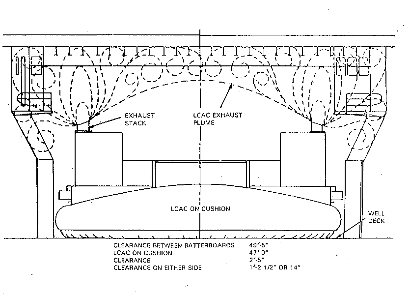
a. LCAC operations require a dry well vice the wet well used in launch and recovery of assault boats. When operating LCACs, well deck personnel need to be constantly aware of the hazards
Figure 1.4-5 LCAC Exhaust Gas Pattern
presented by the high winds and exhaust gases produced by the craft as well as maintaining a continual watch for FOD. Safety precautions for LCAC operations include:
(1) Personnel in the well deck/catwalk are will be required to wear the appropriate lifejackets, safety shoes, safety goggles, protective head covering (flight deck cranial) and double hearing protection
(2) Ensure well deck ventilation supply blowers are operating at full power 30 minutes prior to, during and 30 minutes after craft handling operations
NOTE: On the LHD 1 class, vent plenums are installed on the port and starboard sides of the well deck to vent off fumes from the LCACs
(3) Ship’s company shall complete a FOD walkdown of the well deck, wingwall and flight deck areas and the LCAC crew shall inspect vehicles and the craft for FOD hazards
NOTE: The vehicle ramps and well deck are shall be continually monitored for FOD hazards
(4) The Well Deck Control Officer will ensure that all personnel in the well deck or on the wingwalls are at least 50 feet forward of an operating craft due to the heat of the exhaust gases (Figure 1.4. is an example of the exhaust gases pattern at the sill)
I. TYPES OF BOW RAMPS
1. Hinged bow ramp
a. The hinged bow has a single closure section attached to ship/craft hull structure by a hinge along the bottom edge of the ramp.
b. It forms part of the ship/craft hull bow structure.
c. It provides a water tight closure for the bow opening. Rubber gaskets are installed at the bottom, sides, and sometimes at the top of the housed ramp.
d. It rotates down and away from the ship.
e. In the open (lowered) position, the ramp may be supported by sill bearers on the bow structure or by fixed lengths of wire rope pendants.
f. It may be operated by either using a hydraulic system or a winch and wire rope rigging system.
g. Hinged bow ramps are found on LCVPs, LCM-6s, LCM-8s, LCUs, LCACs.
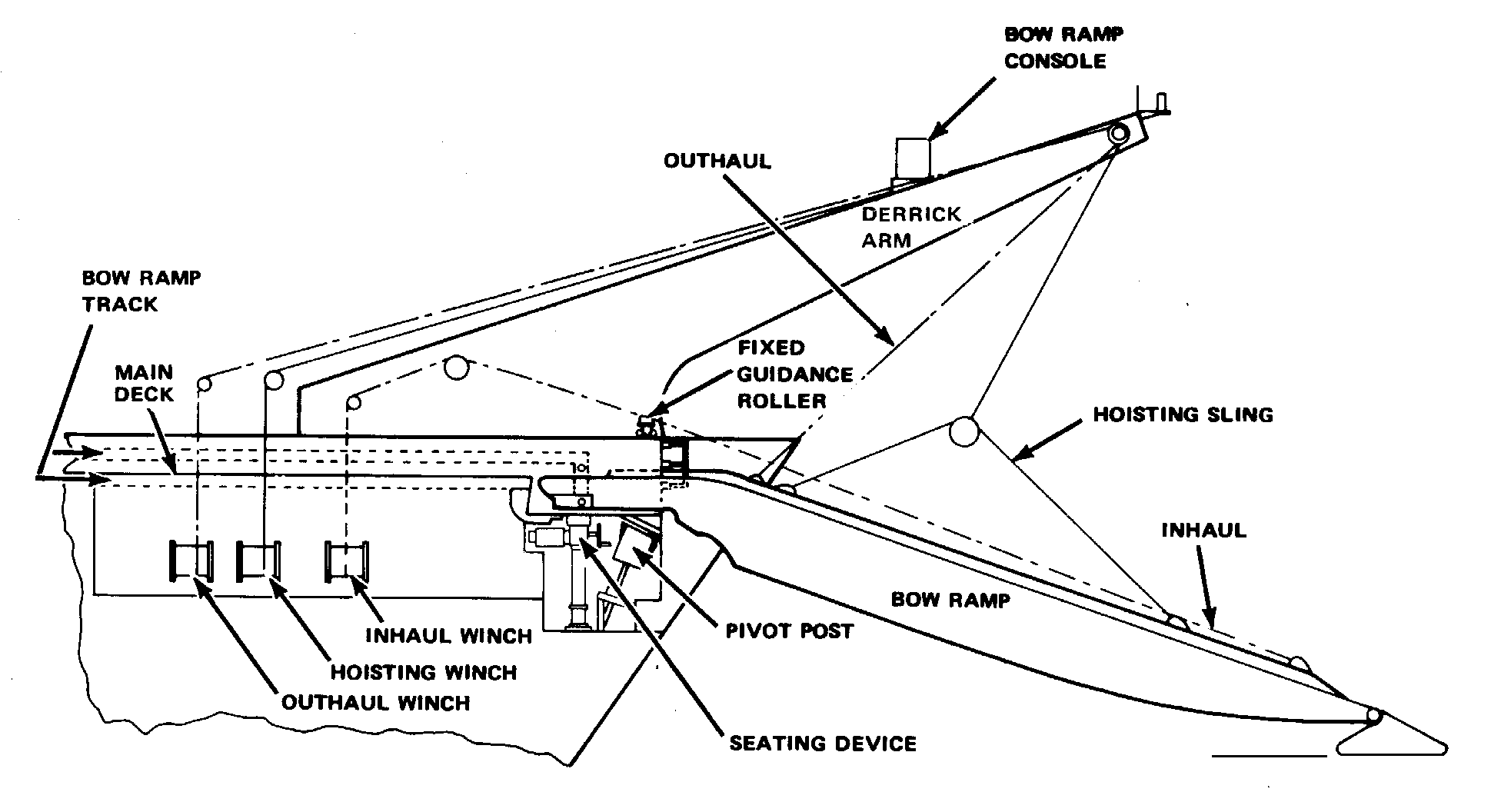
1.4-6 Pivoted Bow Ramp
2. Pivoted Bow Ramp
a. The pivoted bow ramp consists of a roller-mounted bridge structure that is located on the main deck of LSTs when in the stowed position.
b. It is a complex system with the following different parts:
(1) Ramp
(2) Bow doors
(3) Tracks
(4) Winches with wire rope rigging
(5) Fixed and positive guidance rollers
(6) Seating device
(7) Pivot post
(8) Various interlock and limit switches
(9) Interlock control system
(10) Control consoles
c. The ramp is moved and supported by a system of wire rope purchases (a tackle, lever, or device that provides mechanical advantage or power and is also used as an effective hold or position for applying power in moving or heaving around.) and the hoist/outhaul/inhaul winches.
d. When extended, the ramp projects over the bow and is supported from two derrick arms by hoist bridles.
e. Aft end of the ramp is seated on a pivot post recessed in the bow.
f. Although the ramp is deployed ahead, straight out from the ship's centerline, it can be positioned (by the pivot post) 15 degrees to either side.
g. In emergency situations, the ramp may be disconnected and jettisoned onto the beach.
h. When unloaded and stowed, both ramp systems are capable of withstanding Grade A shock.
(1) Equipment is classified Grade A when it is essential for the safety and continued combat capability of the ship. Grade A items will continue to perform their principal function without significant change in performance and will not come adrift.
(2) Equipment is classified Grade B when it is not required for the safety or continued combat capability of the ship. Grade B items are located or arranged to avoid becoming a hazard to personnel or Grade A items.