 Deck Officer
  Deck Officer
 INFORMATION SHEET
STREAM TRANSFER STATIONS
Information Sheet 1.11
INTRODUCTION
Replenishment at sea (RAS) allows the U.S. Navy to conduct sustained operations at sea in accordance with Title 10 of the U.S. Code. It increases the amount of time that a ship can spend at sea without returning to port for stores or fuel. This increased time on station allows more tactical flexibility. As a First Lieutenant/Deck Officer, you must be familiar with the various types of RAS stations, the equipment used at each station, and the safety precautions involved.
REFERENCES
(a) NWP 4-01.4 (REPLENISHMENT AT SEA)
INFORMATION
A. SLIDING PADEYE RECEIVING STATION
1. There are four basic types of receiving stations in use in the U.S. Navy. The sliding padeye receiving station has many advantages. It is easy to rig and operate, its use permits the transfer of loads weighing up to the maximum load limit of the STREAM rig (whereas other types of receiving stations have weight limitations below that of the rig), it allows the receiving ship to transfer heavy loads back to the delivery ship if required, and it provides good control of the load at all points during transfer.
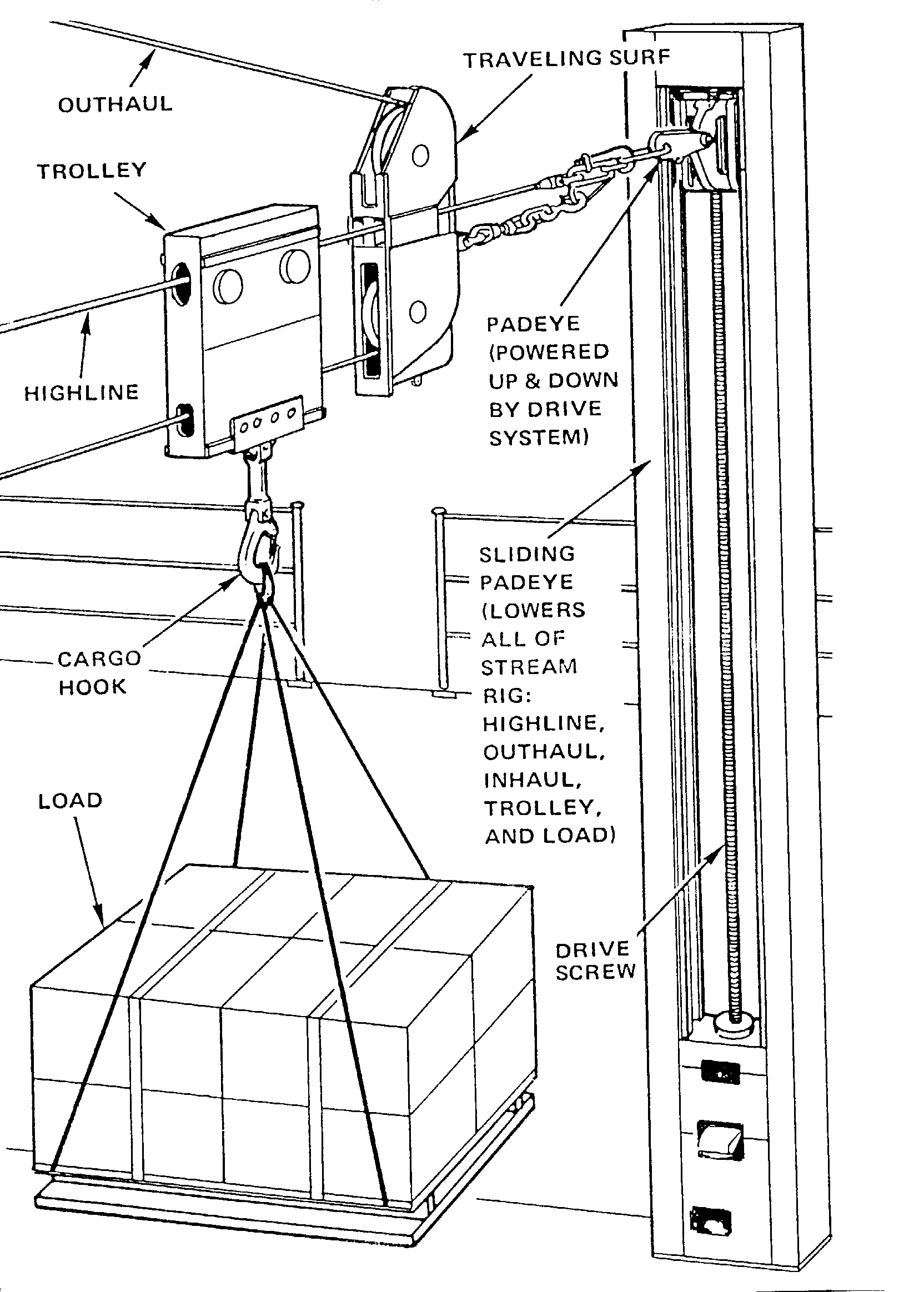
2. There are several types of sliding padeye receiving stations, the most common of which is the bulkhead-mounted. Other types in use include the portable, the retractable, and the overhead stowed. Figure 1.11-1 shows a typical bulkhead-mounted sliding padeye receiving station consisting of the following:
a. Padeye - the padeye is used to secure the highline to the receiving ship.
b. Guide track - the track in which the padeye moves up and down, it is mounted on the kingpost (support structure) of the receiving station.
c. Sliding padeye controls - the sliding padeye is powered to move up and down in the guide track. Lowering the padeye brings the rig close to the deck so that the incoming load can be easily detached. Raising the padeye to the up position allows the trolley to move easily between ships.
3. A cargo drop reel hook is not required if the receiving station is equipped with a sliding padeye. A standard cargo hook is all that is needed.

Figure 1.12-1 Sliding Padeye
4. Operation
a. During the transfer cycle, keep the padeye in the up position so that the load clears the deck edge.
b. When the load is over the landing area, lower the padeye to bring the load to the deck.
c. Lower the padeye until the slings on the load can be easily detached from the cargo hook or load.
d. After the load has been detached, raise the padeye to the up position so that the delivery station can haul the trolley back.
e. The sliding padeye operator should ensure that the receiving area is clear of personnel before lowering or hoisting a load. The operator must control the padeye with caution to avoid slamming the cargo into the deck.
f. The sliding padeye operator should ensure that the padeye is at the top of the guide track before the trolley is moved along the highline.
5. Other types of receiving stations include the fixed padeye, pendant, and STREAM support leg (CV only). The use of a cargo drop reel or the tension/detension method of delivery is required when using one of these types of receiving stations. In the tension/detension method, the highline winch operator will detension the rig in order to lower cargo to the deck on the receiving ship.
6. Some ships are equipped with small electric winches, called gypsy winches, at their receiving stations. Such winches are fitted with a gypsy head (a line handling drum) and are used for handling lines during the rigging of the RAS station. They may also be used for controlling the outhaul on the receiving ship. Gypsy winch operation is similar to that of the inhaul/outhaul winches in the speed control mode (this will be discussed in paragraph C).
B. INHAUL/OUTHAUL WINCH
1. The inhaul/outhaul winches are electrohydraulic hauling winches. The inhaul winch is always located on the delivery ship, and the outhaul winch is usually located on the delivery ship as well. Some types of ships (e.g. UNREP ships, aircraft carriers, and some tenders) are equipped with winches at their receiving station, but this is not common. If the outhaul is controlled by the receiving ship, it is usually hand-tended.
2. The inhaul and outhaul winches at the delivery station move the trolley and suspended load along the tensioned highline. When using one of the STREAM rigs with all tensioned wires, the rig will be set up as follows:
a. The wire rope outhaul is payed out from the outhaul winch and fairled (i.e., guided in such a way as to avoid chafing) through a block at the top of the kingpost at the delivery station.
b. The outhaul is then reeved (i.e., fastened by passing through or around) through a fixture secured at the receiving station. This fixture must be passed to the receiving ship along the highline, and it is called a SURF (Standard Underway Replenishment Fixture).
c. The outhaul is then attached to the outboard side of the trolley (i.e., the side closest to the receiving ship).
d. The outhaul will then be used to move the trolley toward the receiving ship.
e. The wire rope inhaul is permanently rigged on the delivery ship. The inhaul is usually fairled through a deck fixture, reeved through the kingpost and the sliding block, and attached to the inboard side of the trolley. (NOTE: The sliding block is the device at the delivery station that moves the highline up and down like the sliding padeye does at the receiving station.)
f. The inhaul is used to move the trolley toward to delivery ship.
3. The Navy standard hauling winch incorporates the inhaul and outhaul winches in one winch bed. This arrangement is found on most newer UNREP ships.
C. INHAUL/OUTHAUL WINCH OPERATION
1. Wire - shall be type 1, general purpose, class 3, independent wire core, extra improved plow steel, in accordance with federal spec. RR-W-410.
a. Housefall Whip - 800 feet of 3/4-inch wire rope with a thimble eye on one end.
b. Inhaul Whip - 800 feet of 3/4-inch wire rope with a feige type end fitting on one end.
c. Outhaul Whip - For STREAM rigs 1200 feet (or length to fit individual station) of 1/2 inch wire rope with a feige type end fitting on one end.
2. STREAM inhaul and outhaul winches can be operated in two modes: speed control and tension control.
3. Speed Control - just like most cargo winches, inhaul and outhaul winches operated in speed control respond to the movement of the control handle only. The further that the control handle is moved, the greater the speed of the winch.
a. When the winch operator moves the control handle in the "pay out" direction, the winch runs out more wire.
(1) Some inhaul/outhaul winches are equipped with an Anti-Slack Device (ASD) which serves to keep a tension on the line when it is being paid out and to avoid fouling the line on the winch drum. The winch operator must ensure that the ASD, if one is installed, is ON and operating before paying out the inhaul/outhaul in the speed control mode.
b. When the operator moves the handle in the "haul in" direction, the winch reels in wire.
c. When the handle is in the "neutral" (hands-off) position, the internal brake sets and the winch drum should not move.
d. The winch operator must NEVER move the sliding block while the inhaul winch is in speed control.
3. Tension Control - In tension control, the inhaul and outhaul winches respond not only to the movement of the control handle, but also to a tension-sensing mechanism in the winch. When operating the winches in this mode, the internal brake is always released.
a. The major reason for operating the inhaul and outhaul winches in tension control mode is to compensate for the movement of the ships and prevent a "tightline" condition during transfer. Such a condition might occur if the ships moved apart, increasing tension in the inhaul and outhaul wires, and the winch operator could not pay out additional wire rope quickly enough to compensate.
b. In this mode, the operator "sets in" the desired tension by moving the winch control handles. The winch then attempts to maintain the tension ordered by responding to the tension in the lines as measured by the winch's internal device. The outhaul and inhaul winches will now pay out or haul in the wire rope lines automatically as the distance between ships changes.
(1) With the inhaul and outhaul winch controls both set in the "minimum tension" position, the tension on both sides of the trolley will be equalized and the trolley will not move.
(2) Increasing the tension of the outhaul (by moving the control handle in the "increase tension" direction) will cause the trolley to move toward the receiving ship.
(3) Increasing the tension of the inhaul will cause the trolley to move toward the delivery ship.
(4) The trolley will always move in the direction of greater tension.
c. When the winch operator switches the winch to tension control and the control handle is in the "neutral" position, the winch immediately hauls in, applying and maintaining a minimum tension of about 1,000 lb (454 kg) to 1,500 lb (680 kg) in the wire rope.
(1) CAUTION: When inhaul and outhaul winches are put in tension control, they immediately haul in to put 1,000 to 1,500 lbs of tension on the wire ropes. The bitter ends of the inhaul and outhaul must always be properly secured and personnel must be clear of the lines before switching winches to tension control.
d. Then tension-sensing mechanism measures tension in the wire rope, either directly from the wire rope, or through pressure changes in the hydraulic fluid. Moving the control handle in the "increase tension" direction gradually increases the tension in the wire, while moving the control handle to the maximum "increase tension" direction applies 4,500 lbs to 5,000 lbs of tension in the wire.
D. HIGHLINE WINCH AND RAM TENSIONER
1. Wire - shall be type 1, general purpose, class 3, independent wire core, extra improved plow steel, in accordance with federal spec. RR-W-410.
a. Highline - For STREAM rigs the highline is 800 feet of 7/8-inch or 1-inch wire with a poured socket end fitting on one end. For the Wire Highline (non-tensioned) the highline is 800-feet of 3/4 inch wire rope with a thimble eye on one end.
2. The highline winch and ram tensioner are also located at the transfer station on the delivery ship. A brief review of their functions is as follows:

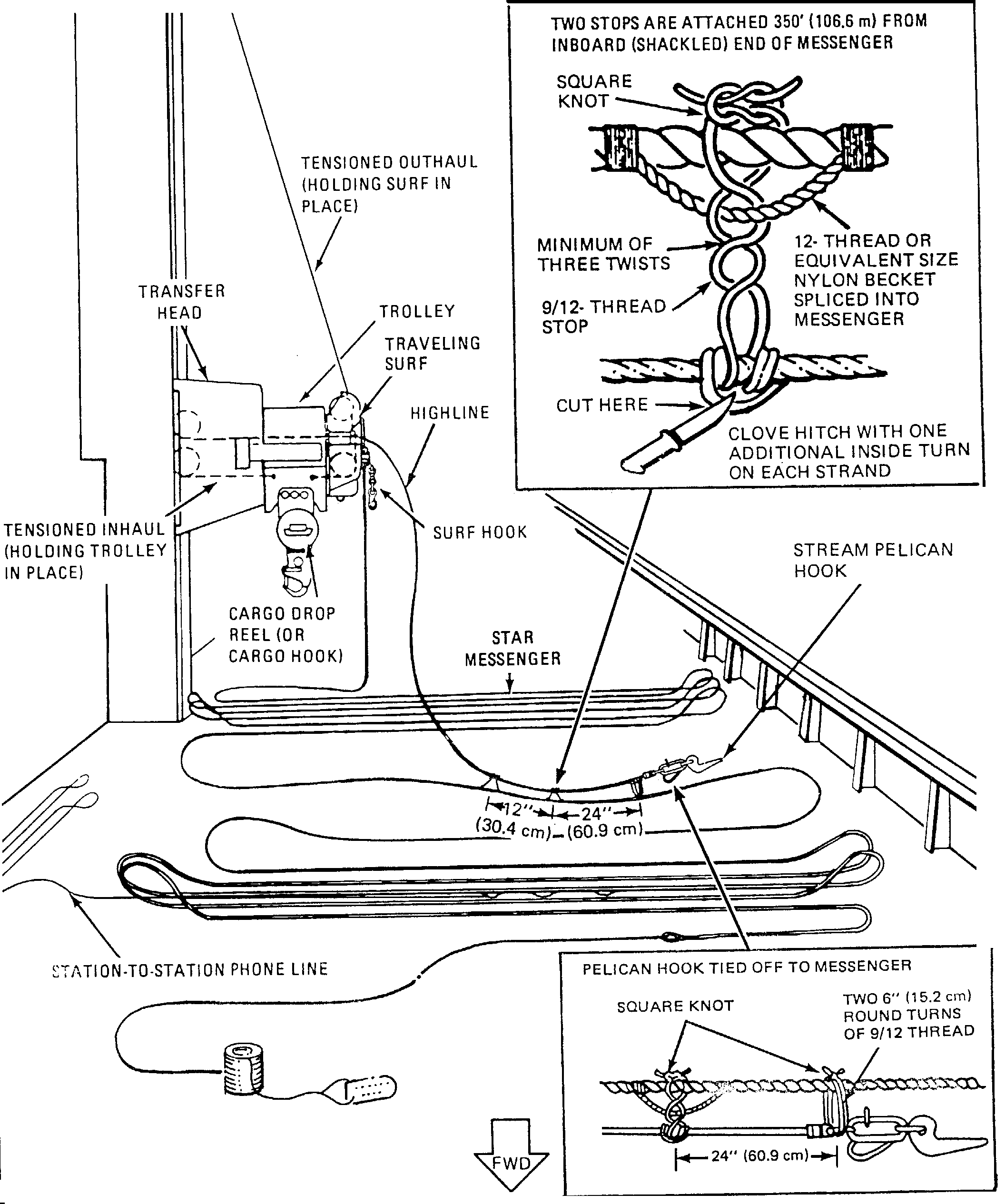
Figure 1.11-2 STREAM w/ Traveling SURF rigging layout
a. Highline winch - The winch that is used to pay out or retrieve the highline. The highline supports the trolley and suspended load. The highline must remain taut/tensioned during cargo transfer in order to provide constant support for the load.
b. Ram Tensioner - A device that keeps the highline taut by adjusting the tension in the highline to compensate for normal ship movement during RAS. It is located between the highline winch
and the kingpost. The ram tensioner consists of a large hydraulic cylinder with an air/oil accumulator.
c. Anti-Slack Device (ASD) - The ASD provides a constant pull on the highline while the line is being passed to the receiving ship. This keeps the highline from tangling up, or fouling on the highline winch drum. The ASD will be located either: (1) between the highline winch and the ram tensioner or (2) outboard of the ram tensioner. THIS IS A SEPARATE ASD FROM THE ONE ON THE INHAUL OR OUTHAUL.
a. Ram tensioners use a phosphate ester fire resistant hydraulic fluid which is safe to use when handled properly and cautiously. Personnel who may come in contact with this fluid should be briefed on the following safety precautions:
(1) Avoid inhalation, ingestion, skin, and eye contact. If exposed, remove contaminated clothing. Immediately wash exposed skin with soap and water, and rinse eyes with water for 15 minutes. Seek medical aid. Launder contaminated clothing immediately.
(2) Keep food, smoking material, and drink away from areas where the fluid is being handled or stored.
(3) Wash hands thoroughly with soap and water immediately after handling the fluid.
(4) Respirators and eye protection are required in the area of leaks which result in fine mist or spray in the air.
(5) Follow the precautions of NAVSEAINST 5100.13 when cleaning up spills or handling phosphate ester fluid.
b. Older ram tensioners may still contain a toxic fluid, sometimes called Cellulube 220A or Fyrquel 220 PM. This fluid contains a highly toxic substance, TRIORTHOCRESYL-PHOSPHATE (TOCP), which can be absorbed into the body through the skin and may affect certain nerve functions. This older, more hazardous fluid may be identified by its green color and should be changed to the current non-neurotoxic fluid at the first opportunity.
E. TRANSFER HEAD CONTROL
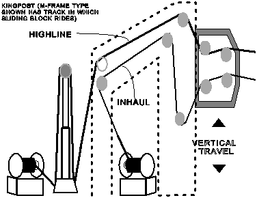
1. The STREAM transfer station is made up of the following major components (see to figure 1.11-3):
a. Kingpost - the kingpost is the support structure for the delivery station. It has a track for the sliding block.

Figure 1.11-3 STREAM Transfer Head
b. The sliding block carries the STREAM transfer head. It is driven up and
down on the track inside the kingpost by means of a chain arrangement or hydraulic piston.
c. STREAM transfer head - This is the device which provides a connection point for the highline and inhaul/outhaul on the delivery ship. Its function is similar to that of the sliding padeye on the receiving ship.
(1) Inside the sliding block and transfer head are sheaves (i.e., pulleys for hoisting or hauling which have a grooved rim for retaining a wire rope) through which the highline and inhaul are reeved. The outhaul block is usually mounted on the kingpost.
(2) The movement of the sliding block and transfer head controls the vertical travel of the highline, trolley, and suspended load.
(a) The transfer head is lowered to the deck for rigging the STREAM station.
(b) The transfer head is raised to the top of the kingpost to lift a load from the deck, transfer it to another ship, and retrieve the trolley.
(c) The transfer head is then lowered far enough to bring the empty cargo hook close to the deck to pick up subsequent loads.